Op-Amp Inverting Amplifier Circuit Diagram: 1K & 10K Build Your Own
Circuit diagram
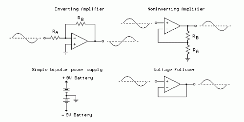
The operational amplifier, or op-amp, is fundamentally a differential amplifier characterized by its substantial voltage amplification, exceptionally high input resistance, and remarkably low output resistance. It possesses a designated “inverting” or (-) input terminal and a separate “noninverting” or (+) input terminal, culminating in a single output signal. Typically, this amplifier is powered utilizing a dual-polarity power supply spanning a voltage range of plus or minus 5 volts to plus or minus 15 volts. A straightforward dual polarity power supply can be assembled employing two 9-volt batteries, as illustrated below.
Operational Amplifier (Op-Amp) Description
Operational amplifiers, often abbreviated as op-amps, are versatile integrated circuits (ICs) designed to perform various amplification and signal processing tasks. They are commonly found in analog circuits due to their high gain, high input impedance, and low output impedance. These characteristics make them ideal for applications where precise amplification and signal manipulation are required. Op-amps are widely used in circuits such as amplifiers, filters, oscillators, and comparators. They are available in a variety of packages and configurations to suit specific needs. The performance of an op-amp is characterized by parameters like open-loop gain, bandwidth, input bias current, and offset voltage. These parameters dictate the amplifier's behavior under different operating conditions. Op-amps are available in different versions to suit specific needs, such as low-power op-amps for battery-powered applications and high-speed op-amps for demanding signal processing tasks. Moreover, the use of op-amps has significantly impacted various fields, including electronics, instrumentation, and control systems.
Inverting Amplifier:
In this arrangement, the op-amp is connected utilizing resistors RA and RB such that the input signal is connected in series with RA, and the output is connected back to the inverting input through RB. The noninverting input is connected to the ground reference or the center tap of the dual polarity power supply. During operation, whenever the input signal shifts positively, the output will move negatively and conversely. The magnitude of the voltage change at the output relative to the input depends on the ratio of the two resistors RA and RB. As the input shifts in one direction, the output will move in the opposing direction, ensuring that the voltage at the inverting input remains constant, or at zero volts in this case. If RA is 1K and RB is 10K and the input is +1 volt then there will be 1 mA of current flowing through RA and the output will have to move to -10 volts to supply the same current through RB and maintain the voltage at the inverting input at zero. The voltage gain in this scenario would be RB/RA or 10K/1K = 10. Note that because the voltage at the inverting input is always zero, the input signal will perceive an input impedance equivalent to RA, or 1K in this instance. For increased input impedances, both resistor values can be amplified.
Noninverting Amplifier:
The noninverting amplifier is configured such that the input signal is directly connected to the noninverting input (+) and the input resistor RA is grounded. Within this configuration, the input impedance seen by the signal is substantially elevated since the input is simply tracking the applied signal and not restrained by a feedback current. As the signal fluctuates in either direction, the output will follow in phase to maintain the inverting input at the same voltage as the input (+). The voltage gain is perpetually greater than 1 and can be calculated from Vgain = (1+ RB/RA).
Voltage Follower:
The voltage follower, also referred to as a buffer, provides a high input impedance, a low output impedance, and unity gain. As the input voltage fluctuates, the output and inverting input will experience changes by equal amounts.
