Build Your Own 220V AC Remote Tester Circuit
Description
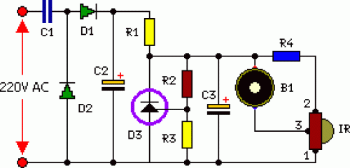
This document details a straightforward tester for verifying the functionality of a wireless television remote. The design is economical and readily assembled. The apparatus utilizes an infrared receiver chip, TSOP1738, as its core component. The operation of the remote control is recognized via an audible tone generated by a buzzer. The circuit exhibits sensitivity and demonstrates a range of roughly five meters. The integrated IR receiver is responsible for detecting, boosting, and decoding infrared signals transmitted by the remote control unit. The piezoelectric buzzer, connected at its output, emits a sound to signal the presence of a signal originating from the remote control unit.
Circuit Diagram:
Parts:
- R1 = 100 Ohm - 1/2W
- R2 = 47K Ohm
- R3 = 47K Ohm
- R4 = 100 Ohm - 1/2W
- C1 = 0.47uF - 275V
- C2 = 470uF - 35V
- C3 = 10uF - 25V
- D1 = 1N4007
- D2 = 1N4007
- D3 = TL431
- B1 = Piezo Buzzer
- IR1 = TSOP1738
Circuit Operation:
As illustrated in the diagram, the output pin 3 of the IR receiver module TSOP1738 (IR1) is typically high, and the B1 is silent. Upon receiving an infrared signal, the output of IR1 drops to a low level, which then causes the B1 to emit a tone, indicating the detection of a signal from the remote control unit, such as a television remote. The complete circuit should be assembled onto a general-purpose printed circuit board and housed within an enclosure. Placement of the IR receiver module on the front panel of the enclosure ensures optimal reception of infrared signals. Prior to soldering or connecting the shunt regulator and IR module, consult the pin configuration reference.
Integrated Circuit Details
The TL431 is a three-terminal adjustable shunt regulator IC. This component is typically used to provide a stable voltage reference, and in this circuit, it's employed as a voltage divider to control the sensitivity of the IR receiver. Its three pins – the inverting input, the non-inverting input, and the output – allow for precise adjustment of the reference voltage. The TL431’s internal circuitry ensures a stable output voltage across varying load currents, contributing to the overall accuracy of the circuit. It’s a common and reliable IC in numerous electronic applications due to its temperature stability and low quiescent current.
