Simple Op-Amp Radio Schematic & Build Guide
Circuit Diagram
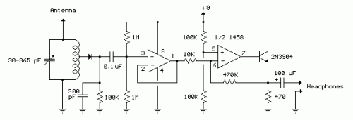
This diagram depicts a crystal radio incorporating an audio amplifier, exhibiting notable sensitivity and the ability to capture multiple prominent radio stations within the Los Angeles area. A minimum antenna length of 15 feet is recommended for optimal performance; however, extending the antenna will result in diminished selectivity and potential interference from adjacent stations. Connecting the inductor to one of its taps instead of the intersection of the capacitor and inductor can improve selectivity when utilizing a long wire antenna. Establishing ground contact is necessary for operation, and a simple solution was discovered—placing the long headphone leads on a concrete surface, such as a concrete slab, provided sufficient ground connection to receive local broadcasts, specifically KNX 1070. The inductor was fabricated by winding 200 turns of #28 enameled copper wire upon a 7/8 diameter, 4 inch length of PVC pipe, resulting in an inductance of approximately 220 uH. Multiple taps were implemented along the inductor’s length, every 20 turns apart, allowing for flexible connections to the diode and antenna, with the optimal configuration found to be 60 turns from the antenna end for the diode. A germanium diode (1N34A) is advised for the best outcome, although silicon diodes can also function if the signal strength is adequate. The carrier frequency is eliminated from the rectified signal at the diode’s cathode through the 300 pF capacitor, and the audio frequency passes through the 0.1uF capacitor to the non-inverting input of the first operational amplifier (op-amp), which serves as an impedance buffer. The second op-amp stage boosts the voltage approximately 50 times, with DC coupling to the initial stage via a 10K resistor. To maintain a stable DC voltage at the transistor emitter (between 3 and 6 volts), it is advisable to utilize resistors with closely matched values (1%) or incorporate a capacitor in series with the 10K resistor.
Alternatively, reducing the overall gain by employing a smaller feedback resistor (470K) can also be implemented. High impedance headphones are generally recommended, though Walkman stereo headphones can also be employed. The circuit draws approximately 10 mA from a 9-volt source. Germanium diodes (1N34A) are readily available from Radio Shack, part number #276-1123.
Operational Amplifiers
Operational amplifiers (op-amps) are integrated circuits that utilize feedback mechanisms to amplify weak electrical signals. They are fundamental components in a vast array of electronic circuits, including audio amplifiers, filters, and instrumentation systems. The op-amps employed here represent a common design for amplifying audio signals, offering a precise and controllable gain. The two op-amps utilized contribute to both the initial impedance buffering and the subsequent gain amplification, ensuring a clean and optimized signal path. Their inherent stability and predictable behavior make them ideal for building robust and reliable audio circuits. They are also relatively inexpensive compared to discrete transistors, making them an attractive option for hobbyists and experimental circuit designers.
Germanium Diodes
Germanium diodes, specifically the 1N34A type, are semiconductor diodes fabricated from germanium. Germanium diodes exhibit a lower forward voltage drop compared to silicon diodes, particularly at lower frequencies. This characteristic is beneficial in crystal radio applications because it minimizes signal attenuation. The 1N34A diode is a general-purpose germanium diode well-suited for this type of circuit. Because of this, it provides superior performance over silicon counterparts in this application. They are widely available at electronic component suppliers like Radio Shack, and their use contributes to the overall sensitivity and effectiveness of the crystal radio design.
