Build Your Own AM Transmitter Circuit – 500KHz to 1600KHz
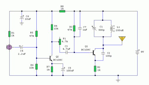
Circuit diagram
Notes:
Operation of a radio transmitter without a valid authorization is prohibited in numerous nations. This circuit is intentionally restricted in its power output, yet it delivers amplitude modulation (AM) of audio signals over the medium wave band. The circuit comprises two distinct sections – a sound amplifier and a radio-frequency oscillator. The oscillator is constructed around transistor Q1 alongside associated elements. The resonant circuit consisting of inductor L1 and variable capacitor VC1 offers frequency selection spanning approximately 500kHz to 1600KHz. These elements can be sourced from obsolete medium wave receivers, if obtainable. Transistor Q1 relies on regenerative feedback to generate oscillation, which is accomplished through linking the base and collector terminals to opposite ends of the resonant circuit. The 1nF capacitor C7 facilitates signal transfer from the base to the top of L1, while capacitor C2, 100pF, guarantees the propagation of the oscillation from the collector to the emitter, and subsequently via the internal base-emitter resistance of the transistor, back to the base. Resistor R2 plays a crucial role within this circuit. It prevents the oscillation from being short-circuited to ground through the transistor’s inherent low emitter resistance and also elevates the input impedance to prevent the modulation signal from being bypassed. The oscillator's frequency is controlled using variable capacitor VC1.
circuit from http://www.zen22142.zen.co.uk/
