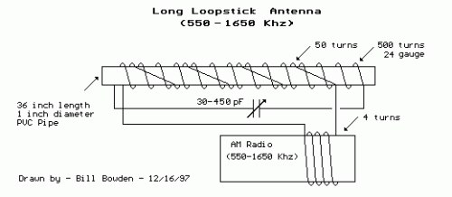
Long Loopstick Antenna Circuit Diagram: 213uH Design
Circuit diagram
A spirally wound device on a 3 foot length of PVC pipe, the long loopstick antenna was a trial to enhance AM radio reception, avoiding extended wires or grounds. It generally performs well, significantly boosting the signal strength of a distant station approximately 130 miles away. An even longer rod antenna would likely deliver superior results if space permits. The required number of turns for the loopstick can be calculated using the single-layer, air-core inductance formula:
Inductance = (radius^2 * turns^2) / ((9*radius)+(10*length))
Here, dimensions are expressed in inches and inductance is measured in microhenries. The expected inductance is around 230 microhenries, suitable for operation with a standard AM radio tuning capacitor (33-330 pF). The 3 foot PVC pipe is wrapped with roughly 500 uniformly spaced turns of #24 copper wire, creating an inductor of approximately 170 microhenries. However, the result was slightly higher (213uH) due to inconsistent winding spacing. A secondary coil of around 50 turns is wound along the length of the pipe above the primary and subsequently connected to 4 turns of wire wrapped directly around the radio. The windings surrounding the radio are arranged so that the radio’s internal antenna rod passes through the external windings. An alternative approach for improved coupling would be to wind a few turns directly around the internal rod antenna within the radio itself; this would necessitate opening the radio. During operation, the antenna should be oriented horizontally relative to the ground and at a right angle to the direction of the target radio station. Fine-tune the radio to a weak signal to discern a definite level of noise, then adjust the antenna capacitor and rotate the antenna to achieve optimal performance. The antenna should also be situated away from devices generating electrical interference, such as lamp dimmers and computer monitors.
