Build Your 73 MHz Hallogene Lamp Remote Control Circuit
Circuit Diagram
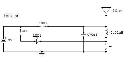
This circuit represents a 73 MHz Hallogene Lamp Radio-Controlled device. The design’s intent is to manage the operational state of a hallogene lamp using a remote control system. Activating the push button on the remote control causes a change in the lamp’s power state; consequently, if the lamp was previously illuminated, it will be extinguished, and vice-versa. Pressing the button again will repeat this action. A LED indicator on the remote control illuminates upon button activation.
The system comprises two distinct circuits. One is the transmitter, or emitter, while the other is the receiver, or the hallogene lamp controller. The input of the lamp controller circuit is connected to a 120VAC power source from the mains to provide it with energy. The hallogene lamp is connected to the output of the circuit to receive the supplied and regulated power for operation and control.
Important considerations for this circuit are the inclusion of two logic components.
Schmitt Trigger NOT Gate (74LS14
The 74LS14 is a versatile digital logic integrated circuit. This specific component acts as a Schmitt trigger, providing hysteresis for reliable switching. Its Vcc pin should be connected to the output of the +5V regulator (7805), supplying the necessary power. The GND pin is connected to the ground reference point of the entire circuit.
JK Flip-Flop (74LS76)
The 74LS76 is a bistable multivibrator, or JK Flip-Flop, a fundamental building block in digital electronics. It’s used to create memory elements and to implement various sequential logic functions. The Vcc pin of the 74LS76 must be connected to the output of the +5V regulator (7805), supplying the device with power. The GND pin is connected to the ground reference point of the circuit.
circuit from http://www.electronics-lab.com/

