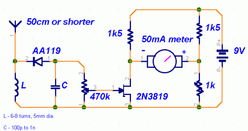
Build Your Own Field-Strength Meter Circuit Diagram
Circuit diagram
Original source:
This circuit was observed in an aged edition of "73 Radio Electronics". Construction was undertaken, yet performance was unsatisfactory, prompting alterations to specific components for enhanced sensitivity.
Description:
This circuit design represents a relatively uncomplicated configuration. The initial stage functions as a crystal receiving circuit. A germanium detector diode – such as the 1N34, though the AA119 diode is frequently encountered across Europe – is essential; silicon diodes are unsuitable for this purpose. The operating frequency is controlled by the values of the inductor (L) and capacitor (C). For FM band and VHF operation, a coil with a diameter of 5mm and 6-8 turns of coated wire measuring 1mm in thickness is recommended. The frequency can be fine-tuned by adjusting the spacing between the coil windings, either increasing or decreasing the gap. The capacitor’s value is less critical, with approximately 100pF being a preferable choice.
2N3819 JFET
The second stage leverages the adaptability of the 2N3819 JFET, a high-impedance amplifier known for its versatility. The 470k potentiometer allows for fine adjustment of the circuit’s sensitivity. A trimmer capacitor is employed for calibration and zeroing the meter. A standard 50mA or slightly smaller ammeter, sourced from a salvaged electronic box, can be utilized for measurements.
Problems:
Acceptable performance levels cannot be anticipated from this uncomplicated detector-based meter. The sensitivity is sufficient for a rudimentary assessment of the power output produced by a transmitter.
Possible uses:
The field-strength meter is particularly useful for determining the optimal operating power of a transmitter. It proves advantageous during stage alignment, as frequently seen in configurations such as the 4W transmitter, or when exploring varied antenna designs.
circuit from http://www.electronics-lab.com/
