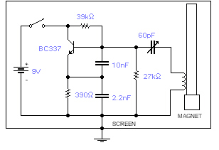
Build Your Own Magnetic Field Detector – Circuit Diagram
Circuit Diagram
This rudimentary oscillator is designed to sense the planetary magnetic field. The ferrite rod and coil originate from a vintage Medium Wave receiver, while a diminutive magnet is affixed to one terminus. Adjust the frequency until a distinct beat note is perceived from a commercial medium wave broadcast station. Any displacement of the ferrite rod will generate an audible tone, directly proportional to the current Earth magnetic field. Careful shielding is paramount. A plastic enclosure, internally cushioned, should be utilized, with copper wires running alongside the rod and connected to earth at a single point. A small aperture is created within the box to facilitate adjustment of the trimmer capacitor using a plastic screwdriver. A suitable alternative to the BC337 might be the 2N2369A, although this substitution has not been experimentally verified.
More about components
Integrated circuits, frequently referred to as ICs, play a crucial role in this circuit's operation. Specifically, the 2N2369A is a general-purpose NPN bipolar junction transistor utilized here. These small, complex chips integrate multiple transistors, resistors, and capacitors onto a single silicon substrate. They are renowned for their compact size, low power consumption, and high reliability. The 2N2369A, in this context, acts as a switching amplifier, controlling the flow of current within the oscillator circuit based on the detected magnetic field variations. The transistor’s gain and switching characteristics are key to the oscillator’s sensitivity and frequency stability. Further information on this transistor can be found in its datasheet. [url=https://www.alldatasheet.com/pdf/2N2369A-datasheet.pdf]Datasheet[/url]
