Build Your 22V Intercom Circuit: A Practical Guide
Description
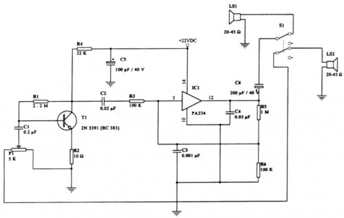
This is a remarkable communication system circuit, suitable for diverse applications. It is designed to function utilizing a voltage of 22V, though experimentation with lower voltages might be worthwhile. For audio input and output, a loudspeaker (ranging from 20 to 45 Ohms) is employed on each side.Circuit diagram
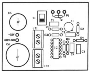
Componets Layout
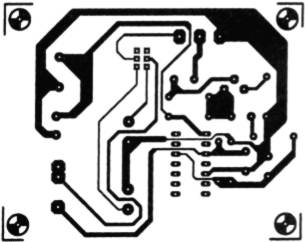
PCB
Parts
- R1: 2.2 M
- R2: 10 Ohm
- R3,R6: 100K
- R4: 22K
- R5: 1M
- C1: 0.2uF
- C2: 0.02uF
- C3: 0.001uF
- C4: 0.05uF
- C5: 100uF/40V
- C6: 200uF/40V
- IC1: PA234 - This integrated circuit is a power amplifier, designed for amplifying audio signals. It typically contains multiple transistors and supporting circuitry to boost the signal strength while maintaining linearity. It is frequently used in audio applications where signal amplification is needed.
- LS1,2: 20-45 Ohm - These loudspeakers are designed to convert electrical signals into audible sound waves. Their resistance range indicates the impedance they can handle effectively.
- T1: 2N3391 (BC383) - This is a general-purpose NPN bipolar junction transistor. It is a common component used in switching and amplification circuits due to its low cost and availability. The BC383 is a specific variant of the 2N3391.
- P1: 5K - This potentiometers provides an adjustable resistance for potentiometers circuit.
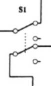
- S1: SW-DPDT * - This is a double pole, double throw switch, allowing for different signal routing configurations.
See here how the SW should be.
*Security Warning: Circuits involving electronic components and electrical power can be dangerous. Exercise caution and follow all safety guidelines. Improper construction or use could result in electric shock, fire, or equipment damage. The author and source of this circuit diagram are not liable for any damages or injuries resulting from the use of this information. This circuit diagram is for informational purposes only. *
circuit from http://www.electronics-lab.com/


