Build Your Own FM Bug: Circuit Diagram & Parts
Description
This straightforward transmission device, when connected to a telephone line, will relay any audio received on that line (excluding the ringing signal) to an FM radio receiver. The operational frequency can be adjusted across a range from approximately 88 to 94 MHz, and the effective transmission distance is roughly 200 feet. It represents a remarkably simple construction project, making it an ideal initial undertaking for novices.
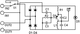
Circuit diagram
Parts
- R1 180 Ohm 1/4 Watt Resistor
- R2 12K Ohm 1/4 Watt Resistor
- C1 330pF Capacitor
- C2 12pF Capacitor
- C3 471pF Capacitor
- C4 22pF Capacitor
- Q1 2SA933 Transistor
- D1, D2, D3, D4 1SS119 Silicon Diode
- D5 Red LED
- S1 SPDT Switch
- L1 Tuning Coil
- MISC Wire, Circuit Board
Notes
- L1 is constructed using 7 turns of 22 AWG wire wound around a 9/64 inch drill bit. Experimentation with the number of turns may be necessary to optimize performance.
- Modifying the coil’s shape through stretching or compression will alter the transmission frequency. The lowest achievable frequency is approximately 88 MHz, while the maximum operational frequency extends to around 94 MHz.
- The green wire connected to the telephone line should be connected to the IN1 terminal. The red wire connected to the telephone line needs to be connected to the IN2 terminal. The green wire from OUT1 is intended for connection to the telephone(s), alongside the red wire from OUT2.
- The antenna consists of a slender (22 AWG) wire, measuring roughly 5 inches in length.
- All capacitors must be rated for a minimum voltage of 250V.
- This transmitter is powered solely by the telephone line and activates only when the telephone is in use. The S1 switch provides a means to disable the transmitter if it is not required.
- If the LED experiences premature failure, a 300 ohm 1/4W resistor can be incorporated in series with it to mitigate this issue.
2SA933 Description
The 2SA933 is a general-purpose NPN bipolar junction transistor frequently employed in audio amplifier circuits and radio frequency applications. Characterized by its relatively high current gain and moderate power handling capabilities, it provides a robust and reliable foundation for constructing the transmitter. Its ability to efficiently amplify signals across a wide frequency range makes it ideally suited for this project. The 1SS119 is a silicon diode, commonly utilized as a rectifier and signal detection device, converting AC signals to DC signals. Its fast switching speed and low forward voltage drop ensure efficient operation in the transmitter circuit.
