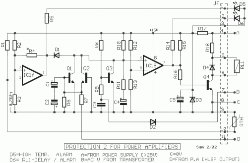
Loudspeaker Protection Circuit Schematic
Description
The circuit provides protection for audio amplifiers and loudspeakers, addressing issues such as continuous voltages at the amplifier output or excessive heatsink temperatures. It employs a binary comparator [ IC1 ], transistors Q1-2, and indicator LEDs D5-6. The circuit's power supply is derived from the positive voltage [ Point A ], stabilized by D3 and R17, at +15V. Point B connects to one of the secondary AC coils of the main transformer. When the main line AC switch is closed, an AC voltage (in the secondary coil) is rectified by D2, creating a negative voltage via R9, supplied to Q3, which then cuts off and begins charging C4 via R10-11. As long as the capacitor charges, the input [+] of comparator IC2B remains at a low level, while the output of IC2B is also low, keeping Q4 off and RL1 deactivated, and D6 on. Only when C4 is charged does IC1B activate, enabling RL1, connecting the loudspeaker to the amplifier output, and turning off D6. When the supply is interrupted, the process reverses, disconnecting the loudspeaker without allowing annoying noises. If continuous voltages exceed +1.7V or are less than -4.8V, Q1 or Q2 activates, lowering the input [+] of IC1B, switching off IC1B and deactivating RL1, and turning off D6. A thermal protection mechanism is also implemented using a PTC (positive temperature coefficient) resistor, RTH (KTY81-122), located on the heatsink above the power transistors. An increase in temperature causes the potential at the input [-] of IC1A to rise above the level determined by the voltage divider R2-3. Once this level is exceeded, the output of IC1A returns to low level, forcing IC2B to change state, turning off RL1 and turning on D5, indicating thermal protection. The thermal protection threshold is set at 70°C. If instability occurs in this stage, the R4 component should be replaced with one of smaller value. The circuit was published in the magazine Elektor 12/95.
The circuit protection system safeguards audio amplifiers and loudspeakers, responding to continuous voltages at the amplifier's output or excessive heatsink temperatures. It relies on a binary comparator [ IC1 ], transistors Q1-2, and indicator LEDs D5-6. Power is supplied from the positive voltage [ Point A ], stabilized by D3 and R17, at +15V. Point B is connected to one of the secondary AC coils of the main transformer. Closing the main line AC switch introduces an AC voltage (in the secondary coil), which is rectified by D2 and creates a negative voltage, via R9, supplied to Q3, which then cuts off and begins charging C4 via R10-11. While C4 charges, the input [+] of comparator IC2B remains at a low level, and the output of IC2B is also low, maintaining Q4 off and RL1 deactivated, and D6 active. Only when C4 is fully charged does IC1B activate, connecting the loudspeaker to the amplifier output, and turning off D6. When the power supply is interrupted, this process reverses, disconnecting the loudspeaker without generating undesirable noises. If the voltages exceed +1.7V or are less than -4.8V, Q1 or Q2 activates, lowering the input [+] of IC1B, shutting off IC1B, and deactivating RL1, and turning off D6. A separate thermal protection segment is included. This segment utilizes a PTC (positive temperature coefficient) resistor, RTH (KTY81-122), positioned atop the heatsink alongside the power transistors. As temperature increases, RTH’s potential at the input [-] of IC1A rises above the level dictated by the voltage divider R2-3. Once this threshold is reached, the output of IC1A returns to a low level, compelling IC2B to change state, turning off RL1 and turning on D5, signaling thermal protection. The temperature limit for this protective function is 70°C. In the event of instability at this stage, the R4 component should be substituted with one having a smaller value. The described circuit was originally published in the Elektor magazine, issue 12/95.
Circuit diagram
Part List
- R1-2=27 Kohms
- R3=1.4 Kohms
- R4=1 Mohms
- R5-14-17=3.3 Kohms
- R6-7=100 Kohms
- R8=47 Kohms
- R9-11=120 Kohms
- R10=470 Kohms
- R12=15 Kohms
- R13=1.5 Kohms
- R15=4.7 Kohms
- R16=33 Kohms
- R18=1.5 Kohms 5W
- RTH=KTY81-122
- C1-2=100uF 63V
- C3=470nF 100V MKT
- C4-5=47uF 25V
- IC1=LM393
- Q1-2-3=BC337
- Q4=BC639
- D1=1N4148
- D2=1N4004
- D3=15V 1.5W Zener
- D4=1N4002
- D5-6=LED
- RL1=24V Relay
