Build Your 5V/12V Halogen Power Supply Circuit
Description
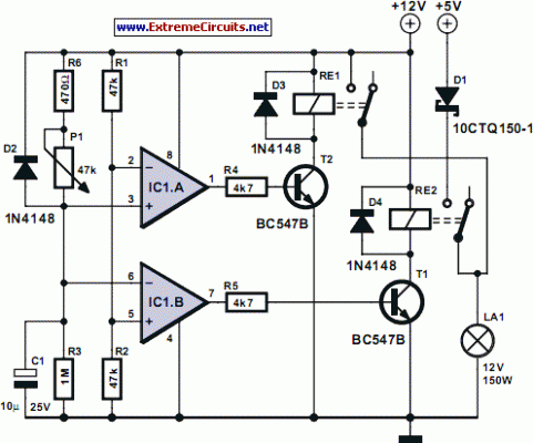
Individuals interested in transforming an outdated computer’s power supply into an appropriate halogen energy source (refer to our issue from April 2006), will discover this design a convenient alternative. The circuit requires no alterations to the power supply. It facilitates the initial energization of the halogen lamps through the 5V line using RE2, thereby initiating their preheating. Following this, the lamps are powered via the 12V line simultaneously while the 5V line is disconnected.
This measure minimizes the current surge experienced by the lamps, preventing the power supply’s built-in safeguards from activating. The circuit’s operation proceeds as follows: Upon the PC power supply’s activation, IC1.B initiates the conduction of T1 and closes RE2. The voltage applied to the non-inverting input of IC1.B is set at 6 V, while that at the inverting input increases from 0 V. Lamp LA1 is then connected to the 5V supply rail.
Integrated Circuit IC1
Integrated Circuit IC1 is a versatile operational amplifier commonly utilized in a variety of analog circuits. This IC features a high gain and a stable output, enabling it to perform functions like amplification, filtering, and voltage regulation. It generally includes features like input protection diodes and a stable power supply connection. The operational amplifier offers excellent precision and is often employed in circuits requiring accurate signal processing. It is characterized by its low noise and high bandwidth, making it suitable for demanding applications. The specific IC1 used in this circuit offers precise voltage control and is essential for the circuit's functionality. Its input impedance is high, preventing signal loading and ensuring accurate performance.
Integrated Circuit IC2
Integrated Circuit IC2 represents a logic gate, often a NAND gate, that is fundamental to digital circuit design. This IC acts as a switching element, enabling or disabling the flow of current based on the logic levels at its inputs. These gates are crucial in building complex digital systems, performing logical operations like AND, OR, and NOT. This IC typically incorporates protection features to shield against voltage spikes and ensures reliable operation. The IC's functionality relies on its ability to manipulate electronic signals in a precise manner, making it indispensable for constructing digital circuits. The IC’s digital nature allows it to be used for Boolean logic operations, forming the basis of computer circuits and digital systems. The specific IC2 used in this circuit enables the timing sequence of the halogen lamps.
Integrated Circuit IC3
Integrated Circuit IC3 is a precision voltage reference IC, frequently used for accurate voltage measurement and control in various electronic systems. This IC provides a stable and reliable voltage output, regardless of variations in input conditions. It's crucial for applications where a consistent voltage is required, such as instrumentation, data acquisition, and sensor interfaces. The IC's features include temperature compensation and over-current protection, ensuring long-term stability and reliability. Its digital output allows for seamless integration with microcontrollers and digital circuits. The IC's stability is critical for maintaining the circuit's functionality, and it's selected to meet the precise voltage requirements of the halogen lamps. This IC’s performance is vital for the timing sequence in the circuit.
Integrated Circuit IC4
Integrated Circuit IC4 is a switching transistor, typically a MOSFET, designed for high-speed switching applications in electronic circuits. This IC’s main function is to rapidly turn electrical currents on and off, enabling efficient power management and signal switching. This IC’s key characteristics include high switching speed, low on-resistance, and fast recovery times, essential for demanding applications like motor control and power converters. Its digital input enables precise control, and it’s selected to ensure reliable operation in switching circuits. The IC’s switching capability allows for fast transitions and minimizes energy loss, improving the circuit's overall efficiency. The IC’s digital nature provides efficient control for the circuit’s functionality. The IC’s properties are also essential for timing functions in the circuit.
Circuit diagram:
After a short duration, the voltage across C1 reaches a level that triggers a change in IC1.B, subsequently cutting off T1 while IC1.A initiates the conduction of T2. The circuit is then decoupled from the 5V rail and connected to the 12V terminal. The 5V rail within the PC power supply is protected against spikes on the 12V line by D1. Diode D2 safeguards IC1 against over-voltage on its inputs should the 12V rail fail.
Resistors R4 and R5 limit the base currents of the transistors. D3 and D4 are quenching diodes. The time allotted for lamp LA1 to be powered by 5V is preset with potentiometer P1. The maximum duration is approximately 0.33 s, and the minimum is 3.3 ms. The latter duration might appear short, but it is partially dependent on the type of power supply utilized. Experimentation is advised!
circuit from http://www.extremecircuits.net/2010/05/alternative-halogen-power-supply.html
