Build Your Own Simple Lie Detector Circuit – 33K, 5K, 1.5K
Description
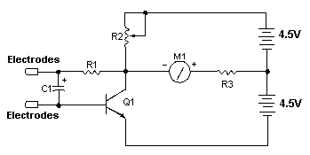
A straightforward deception detector can be assembled in a short period, offering surprising utility when determining the veracity of a statement. While lacking the complexity of instruments employed by experts, this device operates effectively. It functions by assessing skin impedance, which typically decreases during periods of falsehood.
Circuit diagram
Parts
- R1 33K 1/4W Resistor
- R2 5K Pot
- R3 1.5K 1/4W Resistor
- C1 1uF 16V Electrolytic Capacitor
- Q1 2N3565 NPN Transistor
- M1 0-1 mA Analog Meter
- VARIOUS Case, Wiring, Electrodes (Refer to Notes)
Notes
- Electrodes can be alligator clips (though this may cause discomfort), electrode pads (similar to those utilized in medical settings), or simple wires combined with adhesive tape.
- To operate the circuit, affix the electrodes to the back of the subject’s hand, approximately one inch apart. Subsequently, calibrate the meter to display a reading of zero. Pose questions. A change on the meter indicates the subject is not being truthful.
More about components
Integrated circuits, frequently abbreviated as ICs, are fundamental building blocks in this circuit. The 2N3565 transistor, a key component, serves as an electronic switch or amplifier, controlling the flow of current. Transistors are semiconductor devices that can amplify or switch electronic signals and electrical power. They are crucial for implementing logic gates and other digital circuits. This particular transistor is a general-purpose NPN transistor suitable for various switching and amplification applications.
