Build Your Own Static Electricity Negative Ion Detector Circuit
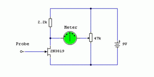
Circuit diagram
Notes
This circuit utilizes the exceptionally high input impedance of a Field-Effect Transistor, and it also illustrates the gate terminal’s vulnerability to minor alterations in voltage. The gate terminal is left open, connected solely to the "probe," which consists of just a few inches of bare copper wire. Without a fixed DC bias, the gate terminal will respond to subtle shifts in voltage or "field strength." It is crucial not to construct this circuit on veroboard or PCB material, as this will diminish the effective gate impedance. Instead, employ an “open” construction technique, soldering each component together. The probe should not be touched directly and is best insulated in a plastic pen sleeve. Furthermore, electrostatic discharge can possess either a positive or negative charge, therefore the meter used should be a centre zero type. Full scale deflection can be 1mA or 250uA for greater sensitivity. Remove the meter and utilize a multimeter to measure the voltage between the FET drain and the preset resistor. Adjust the preset for 0 volts and then replace the meter. This will prevent “bending” of the needle.
More about components
Integrated circuits, often referred to as ICs, are miniaturized electronic circuits packaged onto a single semiconductor chip. In this circuit, a CMOS inverter IC (e.g., a 74HC04) may be used to amplify the signal. CMOS inverters are fabricated using complementary metal-oxide-semiconductor technology, employing both p-type and n-type transistors to achieve switching behaviour. These ICs are characterized by their low power consumption and high integration density, making them suitable for a wide range of applications including logic gates, amplifiers, and memory circuits. The 74HC04, for instance, is a commonly available CMOS inverter IC with a power supply voltage range of 2V to 18V. The IC includes two independent inverters, each capable of producing a high or low output signal depending on the input voltage. The IC's internal circuitry ensures symmetrical switching, providing a clean and stable output waveform. The use of an IC like the 74HC04 offers several advantages including reduced component count, improved circuit reliability, and enhanced performance compared to discrete transistor circuits.
Another possible component is a JFET such as the J2020. JFETs (Junction Field-Effect Transistors) are a type of transistor in which the current flow is modulated by a voltage applied to the gate terminal. They are often employed as switches or amplifiers in low-noise applications. The J2020 is a common example, offering a low gate leakage current and a high input impedance, characteristics desirable for sensitive measurement circuits. The gate voltage controls the current flow between the source and drain terminals, enabling the transistor to amplify weak signals or act as a switch. The JFET’s low input impedance makes it ideal for interfacing with high-impedance sensors or circuits. Due to its construction, this circuit may be operated with a JFET such as the J2020, which provides a high input impedance and low gate leakage current, making it suitable for precise voltage measurements.
Finally, a 555 timer IC could also be included to generate a clock signal for the circuit. The 555 timer is a versatile integrated circuit commonly used to generate precise timing pulses. It operates in astable mode, continuously oscillating between high and low states. When connected to a resistor and capacitor, the 555 timer generates a square wave output, the frequency of which can be adjusted by changing the values of these components. This circuit can be used to generate a reference clock for the circuit or to create a timing circuit. The IC's internal circuitry ensures stable and accurate timing, making it suitable for a wide range of applications including pulse generators, timers, and oscillators. The 555 timer offers several advantages including ease of use, low cost, and wide operating voltage range, making it a popular choice for hobbyists and professionals alike.
If placed in a room, the meter will detect changes in static charge, positive charge deflecting the needle one way and negative the other way. You can test the circuit by placing the unit say 5 feet away from a TV set. When switched on, the meter needle should jump to full scale deflection and then drop down again. If you have a room ioniser, its output can be monitored by moving the detector in front of it. As the detector responds to changes in charge, you may need to move the detector around to see the effect, but it will prove the output from such an ioniser.
circuit from http://www.zen22142.zen.co.uk/
