Build Your AC Line Current Detector (250mA)
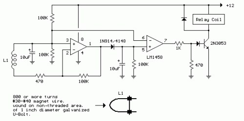
Circuit Diagram
Description
This circuit is designed to identify alternating current (AC) line currents totaling 250 mA or greater without necessitating any direct electrical connections to the power line. The current is measured by routing one of the AC lines through an inductive sensor (L1), constructed from a 1-inch diameter U-bolt and wound with 800 turns of #30 to #35 gauge magnet wire. Alternative iron-based ring or transformer core constructions can also be utilized, provided sufficient space is available for the AC line to pass through the center. To ensure accurate readings, only one of the current-carrying wires – either the line or the neutral – should be inserted through the core, mitigating the effects of opposing magnetic fields. A 2-wire extension cord was utilized for testing, with the twin wires separated by a small distance using an exacto knife, allowing the U-bolt to completely encircle a single wire.
The magnetic pickup (U-bolt) generates approximately 4 millivolts peak when exposed to an AC line current of 250 mA, or for a load consuming roughly 30 watts. The signal produced by the pickup is amplified by a factor of 200 at the output of the operational amplifier's (op-amp) pin 1. Subsequently, this amplified signal undergoes peak detection via a capacitor and diode connected to pin 1. A second operational amplifier functions as a comparator, monitoring voltage increases exceeding the diode's voltage drop. The minimal signal required to trigger the comparator's output to switch positive is around 800 mV peak, correlating to a load of approximately 30 watts. The output 1458 op-amp is restricted to a swing of only a couple volts from ground, necessitating the use of a voltage divider (1K/470) to reduce the no-signal voltage to approximately 0.7 volts. An additional diode is incorporated in series with the transistor base, ensuring it deactivates when the op-amp voltage reaches 2 volts. Some relay chatter may occur if the AC load nears the switching point; therefore, a load of 50 watts or greater is recommended for optimal performance. Increasing the sensitivity can be achieved by adding more turns to the pickup.
Operational Amplifier (Op-Amp)
Operational amplifiers, often abbreviated as op-amps, are fundamental semiconductor devices widely used in electronic circuits. In this particular circuit, a specific operational amplifier, designated as 1458, plays a critical role in signal amplification and comparison. These integrated circuits consist of four main terminals: input pins (in this case, pin 1), output pin, power supply pins, and sometimes a common-mode input pin. The 1458 op-amp in this design is utilized to boost the weak signal from the inductive pickup and to compare this signal with a reference voltage. The 1458 op-amp’s high gain allows it to effectively amplify the signal, and its comparator functionality enables the circuit to detect voltage rises surpassing a specified threshold. These characteristics are essential for the circuit’s function in detecting AC line currents and switching between states. The 1458 op-amp is a versatile component, often employed in a myriad of circuits for signal conditioning, amplification, and control applications. It’s a key ingredient for the proper operation of this circuit.
