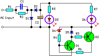
240V AC LED Voltage Indicator Circuit Diagram
Description
This circuit, developed at the request of the user, has demonstrated considerable utility in monitoring changes within a power supply line, specifically the transition from 120V AC to 240VAC. Its application is diverse, particularly when detecting an increase in alternating or direct current supply voltage. LED D3 activates as the line voltage approaches 120V and continues to remain illuminated even with a 240V supply. Conversely, LED D6 remains lit only when the line voltage is approximately 240V and persists due to the latching action of transistors Q1 and Q2 alongside the associated components. Capacitors C1, D1, and D2 operate within a voltage range of 4.5V - 6V, providing the necessary low DC voltage to enable proper function of the latch circuit and the LEDs.
Circuit diagram:
Parts:
- R1_____________470R 1/2W Resistor
- R2_____________220K 1/4W Resistor
- R3,R7__________470R 1/4W Resistors
- R4_______________1K 1/4W Resistor
- R5_______________2K2 1/4W Resistor
- R6_____________330R 1/4W Resistor
- C1_____________330nF 630V Polyester Capacitor
- C2______________10µF 25V Electrolytic Capacitor
- D1,D2________1N4007 1000V 1A Diode
- D3,D6___________LEDs (Color and shape at will)
- D4_________BZX79C10 10V 500mW Zener Diode (See Notes)
- D5___________1N4148 75V 150mA Diode
- Q1____________BC547 45V 100mA NPN Transistor
- Q2____________BC557 45V 100mA PNP Transistor
Notes:
- The D4 value may necessitate adjustments to permit precise switching of the circuit at the selected voltage. In such instances, it is advisable to experiment with values within the 8.2V - 15V range.
- Warning! The circuit is connected to 240VAC mains, therefore certain components on the circuit board are subject to a hazardous electrical potential! Avoid contact with the circuit while it is energized and ensure it is housed within a protective plastic enclosure.
