22KHz Insect Repellant Circuit Diagram: Build Your Own!
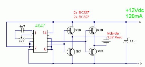
Circuit diagram
Notes:
Discourage unwelcome pests from your Yard this Season utilizing this pest deterrent circuit. Developed by Graham Maynard, the electrical system incorporates a phase-locked loop (CMOS 4047) configured as a 22kHz oscillator. The signal’s amplitude is increased through a pair of complementary output transistors and subsequently feeds a Motorola 3.25 inch Piezo element. The current draw reaches approximately 120mA, necessitating an external power supply for optimal operation.
The Piezo device employed was a typical 85mm square Motorola Horn, Maplin part number WF09K or WF55K. These components possess a frequency response of +/-3dB extending up to 28kHz.
Integrated Circuits – CMOS 4047
The core of this circuit relies on the CMOS 4047 integrated circuit. This is a versatile and commonly used phase-locked loop (PLL) IC. It’s a small, surface-mount device featuring a high-speed, low-power PLL. It’s predominantly deployed in applications requiring precise frequency generation and control, such as oscillators and frequency synthesizers. Its key characteristics include a relatively high switching speed and low power consumption, making it suitable for various electronic systems. This IC provides a stable and accurate reference frequency for the entire circuit.
circuit from http://www.zen22142.zen.co.uk/
