Build Your 11-22kHz Ultrasonic Dog Whistle Circuit
Description
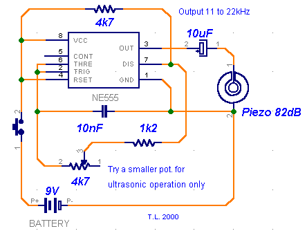
It is widely acknowledged that numerous animal species exhibit heightened sensitivity to high-frequency sounds beyond the range perceived by humans. Many commercially available pest deterrents, operating on this principle, are accessible, predominantly functioning within the 30 to 50 kHz spectrum. My objective was to design a somewhat distinct and considerably more powerful audio frequency/ultrasonic sound generator, specifically intended for training canines. Consider the potential applications – you could discourage your pet from excessively barking during nighttime hours or effectively manage aggressive dogs (and one could reasonably presume burglars would benefit from such a device). Based on research, dogs and other mammals of similar stature display markedly different behaviors compared to insects. They typically respond most effectively to frequencies ranging from 15 to 25 kHz, with older animals proving less susceptible to elevated tones. Consequently, a standard pest repeller would likely prove ineffective, as dogs lack the auditory capacity to hear it. Therefore, I resolved to construct a new circuit (utilizing the established 555 timer) incorporating a variable pitch and a relatively loud 82 dB miniature piezo buzzer. The circuit's construction is straightforward and achievable within approximately half an hour. While component values are not strictly critical, it’s vital to recognize that alterations to these values will likely modify the operating frequency. The potentiometer controls the pitch: increased resistance corresponds to a lower frequency. Given that various dogs respond differently to different frequencies, some experimentation is almost certainly required to optimize this compact circuit. The circuit’s schematic is illustrated below:
Circuit diagram
Despite the circuit’s simplicity, there exists one crucial element. The 10nF (.01) capacitor is paramount, as it also determines the frequency. Many ceramic capacitors exhibit considerable instability, with a 20% tolerance being a common occurrence. Higher capacitance translates to a lower frequency and vice versa. For precise alignment and adjustment, an oscilloscope would be beneficial. Since I do not possess one, I utilized Winscope. Although limited to a maximum of 22 kHz, it provides sufficient visualization of the circuit’s operation. Etching a PCB is unnecessary for this project; a perf board is perfectly suitable. Test the circuit to observe its response at varying frequencies. A 4.7kΩ potentiometer, in conjunction with a 10nF (or slightly larger) capacitor, yields a frequency range of approximately 11 to 22 kHz, which should be adequate. Install the circuit within a small plastic enclosure and, optionally, integrate a LED pilot light. Power consumption is minimal, and a 9V battery should provide extended operation. Potential future exploration: I am developing an amplified version of the whistle to produce a louder beep. All previous attempts have unfortunately been unsuccessful, as high-frequency performance tends to degrade dramatically when employing the 555 timer. Perhaps a frequency doubling circuit could be implemented – however, I lack definitive information and have exhausted my ideas. An alternative, slightly more advanced project could involve a basic “anti-bark” device with a sound-triggered (clap) switch, which initiates the ultrasonic buzzer immediately upon the dog’s bark.
circuit from http://www.zen22142.zen.co.uk/
