Build Your Own Telephone Recorder Circuit – 2N4954 Project
Telephone Recorder
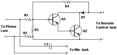
This compact circuit facilitates the automatic recording of telephone conversations. The apparatus is connected to the telephone line, the tape recorder’s microphone input, and the recorder’s remote control port. It monitors the voltage present within the phone line and initiates recording when the voltage decreases to 5 volts or lower.
Circuit Diagram
Components
- R1 270K 1/4 W Resistor
- R2 1.5K 1/4 W Resistor
- R3 68K 1/4 W Resistor
- R4 33K 1/4 W Resistor
- C1 0.22uF 150 Volt Capacitor
- Q1, Q2 2N4954 NPN Transistor
- D1 1N645 Diode
- Various Wire, Connectors Suitable for the Jacks on the Recorder, Board, and Phone Plug
Notes
- The circuit can be positioned in various locations along the telephone line, including within a telephone handset.
- Certain jurisdictions mandate informing individuals engaged in conversations that the dialogue is being recorded. Most recorders accomplish this through an audible beep-beep signal. Furthermore, obtaining authorization from the telecommunications provider may be necessary before connecting any devices to their network lines.
More about components
This circuit employs integrated circuits for enhanced functionality. Specifically, the 2N4954 NPN transistors are utilized as amplifiers and switches within the recording system. These ICs, characterized by their robust performance and low saturation voltages, provide efficient current amplification and switching capabilities. They are essential for controlling the recording process and ensuring signal integrity.
