Build Your Own FET Audio Mixer Circuit – 9V Power
Description
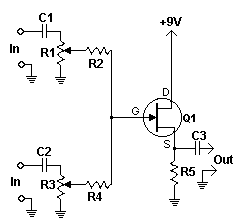
This basic circuit combines two or more channels into a single channel (e.g., stereo into mono). The design accommodates a varying number of channels, ranging from a minimal to a substantial quantity, and exhibits minimal power consumption. The mixer is presented with two inputs, however, it’s readily adaptable to include an unlimited number of channels through replication of the distinct “sections” highlighted within the schematic.
Circuit diagram
Parts
- R1, R3 10K Potentiometer
- R2, R4 100K 1/4 W Resistor
- R5 6.8K 1/4 W Resistor
- C1, C2, C3 0.1uF Capacitor
- Q1 2N3819 Junction FET
- MISC Wire, Shielded (Metal) Case, Phono Or Other Plug For Output
Notes
- The design can incorporate any number of channels needed. This is achieved by duplicating the input "sections," as clearly demonstrated on the schematic. A particular instance of this mixer utilized a staggering 25 inputs!
- A shielded enclosure is likely required to mitigate hum and prevent oscillations.
- The circuit is suitable for operation using a single 9 volt battery.
More about components
2N3819 Junction FET
The 2N3819 is a commonly used N-channel Junction Field-Effect Transistor (JFET). This particular device is a planar-type JFET, known for its good performance and reliability. It’s a three-terminal device consisting of a Gate, Drain, and Source. The Gate terminal controls the current flow between the Drain and Source. JFETs are often employed in applications requiring precise current control and are found in audio amplifiers, instrumentation, and switching circuits. Its characteristics, including its transconductance and input impedance, make it suitable for a wide range of applications.
