Three Channel Audio Mixer Circuit Design Blueprint
Description
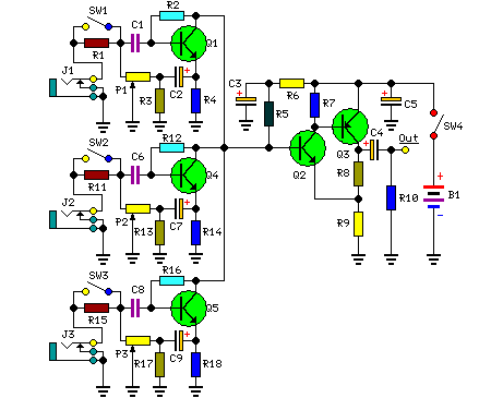
The adaptable Portable Mixer design showcased on these webpages has garnered considerable attention amongst hobbyists, however, certain correspondents expressed a desire for a simpler apparatus, primarily intended for the mixing of mono signals. This design is intended to satisfy those requirements, incorporating three inputs featuring adjustable high/low sensitivity settings and distinctive level-control circuitry. This configuration provides generous overload protection and minimal noise levels, correlating directly with the gain adjustments. Its low power consumption, achieved through a straightforward five-transistor arrangement, enables operation for extended durations using a standard 9V PP3 battery.
More about components
The circuit utilizes three integrated circuits—BC550C, BC547, and BC557. These components are general-purpose NPN bipolar junction transistors commonly employed in a diverse range of electronic circuits. BC550C and BC550C are particularly prevalent, offering reasonable gain and current capabilities. BC547 and BC557 represent variations of these transistors, often selected for their specific characteristics such as improved stability or current handling. Their integration simplifies circuit construction and offers reliable performance within this mixing application.
Circuit diagram:
Parts:
- P1 = 5K
- P2 = 5K
- P3 = 5K
- R1 = 180K
- R2 = 2M2
- R3 = 750R
- R4 = 1K
- R5 = 15K
- R6 = 220R
- R7 = 1.5K
- R8 = 820R
- R9 = 150R
- R10 = 100K
- R11 = 180K
- R12 = 2.2M
- R13 = 750R
- R14 = 1K
- R15 = 180K
- R16 = 2M2
- R17 = 750R
- R18 = 1K
- C1 = 1µF-63V
- C2 = 100µF-25V
- C3 = 220µF-25V
- C4 = 100µF-25V
- C5 = 220µF-25V
- C6 = 1µF-63V
- C7 = 100µF-25V
- C8 = 1µF-63V
- C9 = 100µF-25V
- Q1 = BC550C
- Q2 = BC547
- Q3 = BC557
- Q4 = BC550C
- Q5 = BC550C
- B1 = 9V PP3 Battery
- J1,J2,J3 = 3mm Mono Jack sockets
- SW1,2,3,4 = SPST Toggle or Slider Switches
Notes:
- When SW1, SW2, or SW3 are open, the input sensitivity is suitable for high-output devices such as CD players, tuners, tape recorders, iPods, miniDisc players, and computer audio outputs, respectively.
- When SW1, SW2, or SW3 are closed, the input sensitivity is suited to low-output, low-impedance moving coil or electret microphones.
- Occasionally, locating a 750 Ohm resistor for R3, R13, and R17 may prove difficult. In such instances, two 1.5K resistors connected in parallel can be employed as a substitute for each item.
- To construct a stereo mixer, all components must be duplicated, excluding R6, C3, C5, SW4, and B1.
