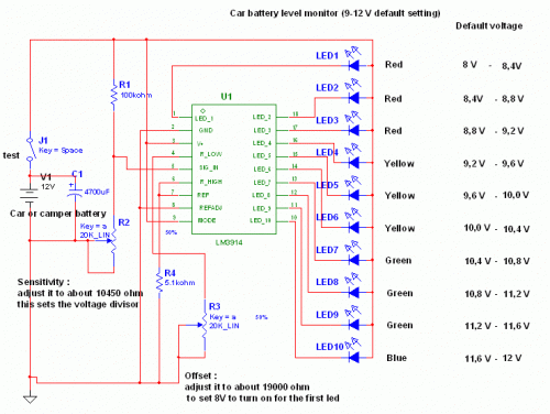
Build Your Own 12V Car Battery Tester Circuit
Circuit Diagram
This circuit incorporates the widely available and straightforward LM3914 integrated circuit. This component is notably simple to operate, eliminating the necessity for voltage regulators (it possesses an integrated voltage regulator) and can be powered by a diverse range of sources.
LM3914 Integrated Circuit
The LM3914 is a versatile analog integrated circuit commonly employed in voltage monitoring and sample-hold applications. It's a three-channel, high-speed, sample-and-hold amplifier. This IC consists of three independent amplifier stages, each offering high gain and speed. It is utilized for converting varying analog signals into a stable, representative DC voltage. It operates from a wide input voltage range and features a low input bias current, making it suitable for precise voltage measurement in various applications. The IC's internal circuitry includes a voltage reference, a high-speed amplifier, and a sample-and-hold circuit, providing a robust solution for accurately measuring and holding analog signals.
This circuit is very easy to explain:
When the test button is pressed, the car battery voltage is fed into a high-impedance voltage divider. The objective is to reduce 12V to 1.25V (or lower values to lower values). This method is superior to simply allowing the internal voltage regulator to determine the 12V sample voltage because the regulator cannot reliably maintain 12V when the voltage drops below it (linear regulators only perform a step-down function). Wiring the regulator without adjustment provides a stable 1.25V, which is then fed into the precision internal resistor cascade to generate sample voltages for the internal comparators. The default configuration enables measurements of voltages between 8 and 12V, though it can also measure voltages from 0V to 12V by adjusting the offset trimmer to 0 (however, under 9V, your car might not start). A smoothing capacitor (4700uF 16V) is employed to absorb Electromagnetic Field (EMF) noise produced by the ignition coil when measuring the battery during engine operation. Diesel engines do not necessitate this capacitor, though its inclusion is recommended for comprehensive measurement accuracy. To obtain a point graph instead of a bar graph, disconnect pin 9 on the IC (MODE) from power.
The calculations are simple (default)
- For the first comparator, the voltage is: 0.833 V corresponding to 8 V
- * * * * * * voltage is: 0.875 V corresponding to 8.4 V
- For the last comparator, the voltage is: 1.25 V corresponding to 12 V
circuit from http://www.electronics-lab.com/
