Build Your Vehicle Battery Voltage Indicator Circuit
Description
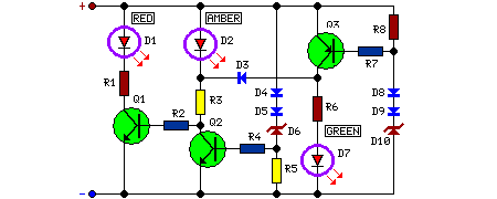
By connecting this circuit to a vehicle’s battery, the available voltage can be readily observed at any given moment. Monitoring battery voltage is beneficial for motorists, allowing them to assess the battery’s capacity to supply current, and to verify the performance of the dynamo or alternator. The LED threshold voltages are defined utilizing two Zener Diodes (D6 & D10) alongside two additional Diodes configured in series (D4, D5 and D8, D9 respectively), which add approximately 1.3V to the standard Zener voltage level.
Circuit diagram:
Parts:
- R1 = 1k
- R2 = 100K
- R3 = 1k
- R4 = 3.3K
- R5 = 3.3K
- R6 = 1k
- R7 = 3.3K
- R8 = 3.3K
- Q1 = BC547
- Q2 = BC547
- Q3 = BC557
- D1 = Red Led
- D2 = Amber Led
- D3 = 1N4148
- D4 = 1N4148
- D5 = 1N4148
- D6 = BZX79C10
- D7 = Green Led
- D8 = 1N4148
- D9 = 1N4148
- D10 = BZX79C12
More about components
Zener Diodes (D6 & D10), employed in this circuit, are semiconductor devices that exhibit a specific voltage across them when reverse biased. Specifically, D6 is a BZX79C10, a common Zener diode offering a stable 10V reference voltage. Similarly, D10 is a BZX79C12, providing a fixed 12V reference. These diodes are crucial for setting precise voltage thresholds for the LED indicators, ensuring reliable operation and accurate monitoring of the battery's state.
Notes:
- The Red LED (D1) illuminates when the battery voltage drops below 11.5V, signifying a depleted battery charge.
- The Amber LED (D2) activates within the 11.5 - 13.5V range, indicating a healthy battery condition when the motor is not in use. However, if the motor is running, this LED signals a lack of charging from the dynamo or alternator.
- The Green LED (D7) becomes illuminated when the battery voltage reaches 13.5V or greater, confirming a normal condition with the motor running and the dynamo or alternator actively charging the battery.
