Car Battery Warning Circuit: Build Your 12V Indicator
Description
This i-TRIXX circuit can prevent a significant amount of trouble for those who go on holiday in a caravan. It would be a detrimental factor on holiday enjoyment when one is ready to depart camping and discovers that the battery has been depleted, rendering the car unable to start. This inconvenience can be avoided if one is warned in advance by an illuminated LED when the battery charge threatens to become too low.
More about components
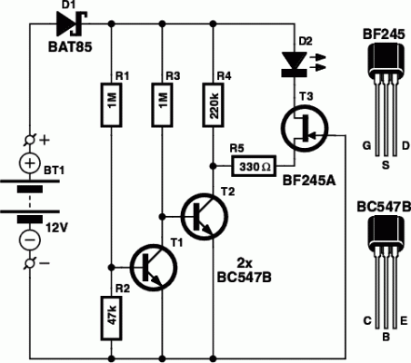
Transistors T1 and T2 play a crucial role in this circuit. T1 and T2 are NPN bipolar junction transistors. These transistors are used as switches, controlled by the voltage of the battery. T1 acts as a voltage-controlled current source, while T2 is a general-purpose transistor. They are essential components for controlling the LED’s brightness and ensuring a reliable warning indicator.
Circuit diagram:
The setting of T1 and T2 determines whether LED D2 will light up when the battery voltage drops below a certain level. Junction FET T3 is utilized as a current source in an attempt to maintain the current through the LED as constant as possible. In this way, the indicator remains lit even when the battery is in a state of very deep discharge (< 4 volt). The LED is a low-current type that remains very bright at a very small current (1 to 2 mA). Voltage divider R1 and R2 have been calculated such that T1 will start to conduct when the battery voltage is greater than 12 V.
If you think this threshold is too high (or: if you think that you can still start your car with a lower battery voltage), then you can reduce the value of R2 or replace it with a 50-k preset (connected as an adjustable resistor). When T1 conducts, the base current to T2 is interrupted and the collector of T2 will become high through R4. In this state T3 does not conduct and the LED is off. When the battery voltage drops below 12 V, T1 will block and T2 will start to conduct. R5 is now connected to ground via T2 which turns T3 into a current source of about 2 mA that drives the LED.
There is, of course, a transition region during which the current through the LED slowly increases; after all, T1 and T2 do not switch with in?nite gain! In our prototype the LED changed from fully off to fully on at a voltage variation from 12 to 11 V. As a bonus, a partially illuminated LED gives a rough indication as to how much the voltage actually is. Diode D1 prevents the circuit from inadvertently giving up the ghost if the circuit is connected incorrectly to the battery (reverse polarity). In practice, because of variations in the specifications of the transistors, the threshold and the current level through the LED can be different.
Test the circuit thoroughly before using it. If you want a brighter indicator, you can increase the current through the LED by replacing T3 with a BF245B or BF245C. When the LED is off, the current through the circuit is barely 30 µA at a battery voltage of 14.4 V. With the LED is on and at a battery voltage of about 10 V, the current consumption is about 2 mA. Even with an illuminated LED, the circuit is not likely to be the cause of a flat battery. Even a good quality battery will have a self discharge rate which is many times greater than the maximum current consumption of this circuit!
circuit from http://www.extremecircuits.net/2010/04/battery-indicator-circuit-for-caravan.html
