Build a 200V Buzz Coil with a 556 Timer
Description
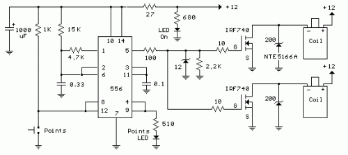
This circuit is designed to generate a buzzing effect using a standard automotive ignition coil. A 556 dual timer serves to define the frequency and duty cycle of the coil's current flow. One of the timers functions as an oscillator, producing a 200 Hz rectangular wave intended to manage the (IRF740 MOSFET) operation, while the second timer regulates the oscillator’s activation and deactivation, mirroring the behavior of traditional breaker points – closed indicates an ‘on’ state. Consequently, a consistent stream of sparks emanates from the ignition coil, spaced approximately 5 milliseconds apart when the breaker points are engaged.
Circuit diagram
Operation:
The pins 8 and 12 of the dual timer are utilized as the threshold and trigger inputs, respectively, and they receive signals from the breaker points, generating an inverted signal at the timer’s output (pin 9). When the breaker points are connected to ground, pin 9 exhibits a high voltage, and conversely, when they are open, pin 9 displays a low voltage. This signal controls the reset line (pin 4) of the second timer, holding the output at pin 5 low as long as pin 4 remains low and pins 8 and 12 are both elevated (breaker points open). The 15K and 4.7K resistors, along with the 0.33uF capacitor, are integral timing components that determine the frequency and duty cycle of the second timer, resulting in a duration of approximately 4 milliseconds for the positive half-cycle and 2 milliseconds for the negative half-cycle. During the positive time interval, the MOSFET gates are maintained at a high voltage, leading to an increase in the ignition coil current, reaching approximately 4 amps, representing approximately 80 millijoules of stored energy which is discharged into the spark plug when the timer output (pin 5) transitions to ground, deactivating the MOSFET. A 12 volt zener diode is positioned at the junction of the 10 and 27 ohm resistors to ensure the MOSFET gate input never exceeds 12 volts or dips below -0.7 volts. A 200 volt/5 watt zener is used at the MOSFET drain to limit the voltage to +200 and extend the duration of the spark. This circuit operates reliably even with a shorted plug, however, running the circuit without a load (such as the plug wires being disconnected) may result in a failure due to a significant portion of the power being absorbed by the zener diode. Alternatively, a transient voltage suppressor (TVS) such as the 1.5KE200A or 1.5KE300A can be used in place of the zener diode; this component is generally preferred as it offers improved performance, though it may be more challenging to source.
Integrated Circuit Detail: 556 Dual Timer
The 556 dual timer is an integrated circuit (IC) belonging to the 555 series, a family of versatile timer ICs. This particular dual timer consists of two independent timer chips within a single package. It’s a popular choice for building timing circuits due to its simplicity, stability, and relatively low cost. The 556 dual timer features two independent one-shot timers, each employing a 555 timer core. The IC incorporates various control inputs such as trigger, reset, threshold, and discharge. It’s commonly used in circuits requiring precise timing intervals, such as oscillators, timers, and pulse generators. Its robustness and ease of use have made it a staple in electronics projects for decades. The 556 dual timer typically operates from a supply voltage ranging from 4.5V to 19V, offering a wide range of applications and flexibility. The IC’s performance is influenced by external components, making it essential to select appropriate resistors and capacitors for optimal operation. This IC is often favored for its reliability and readily available replacement parts.
