CDI Ignition Circuit: 340V Capacitor Discharge Design
Description
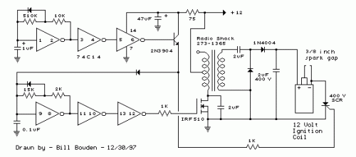
The CDI ignition system generates an electrical arc from an ignition coil through the discharge of a capacitor. A 2µF capacitor is charged to approximately 340 volts, and its discharge is managed via a Silicon Controlled Rectifier (SCR). A Schmitt trigger oscillator (74C14) alongside a MOSFET (IRF510) are utilized to regulate the low-voltage side of a small (120/12 volt) power transformer. A voltage doubler configuration is implemented on the high-voltage side to elevate the capacitor's voltage to approximately 340 volts. A comparable Schmitt trigger oscillator is employed to initiate the SCR at a frequency of around 4 times per second. The power supply is deactivated during the discharge period, ensuring the SCR ceases conduction and returns to its blocking state. A diode connecting from the 3904 to pin 9 of the 74C14 interrupts the power supply oscillator when discharging. This system consumes only about 200 milliamps from a 12-volt source, yet it delivers almost double the energy of a standard ignition circuit. The voltage generated by the coil is approximately 10KV, achieved with a 3/8-inch spark gap at standard air temperature and pressure. The spark frequency can be increased to potentially 10 Hertz without a significant loss in spark intensity; however, this is limited by the low-frequency power transformer and the oscillator's duty cycle. To achieve faster spark rates, a higher-frequency and lower-impedance power supply would be required. It is important to note that the ignition coil is not connected to ground and presents a shock hazard on all its terminals. Exercise caution when operating this circuit. An alternative method for connecting the coil involves grounding the (-) terminal and positioning the capacitor between the cathode of the rectifier diode and the positive coil terminal. The SCR is then placed between ground and the +340 volt side of the capacitor. This configuration diminishes the shock risk and is the customary arrangement in automotive applications.
More about components
The 74C14 is a versatile Schmitt trigger IC, commonly used for oscillator circuits. It provides hysteresis, creating a switching threshold, which is essential for generating stable and predictable timing signals. Its operation is based on comparator circuits that respond differently to signals above and below a defined threshold. This allows for precise control over switching timing and provides a stable reference point for oscillator circuits. The IC is manufactured by Texas Instruments and offers a compact solution for building a range of timing circuits.
Silicon Controlled Rectifier (SCR)
A Silicon Controlled Rectifier (SCR) is a semiconductor device that conducts current when a specific trigger voltage is applied and remains conductive until a turn-off signal is applied. It is essentially a three-terminal device—an anode, a cathode, and a gate. The SCR is characterized by its ability to rapidly switch between conducting and non-conducting states, making it ideal for controlling power and switching applications. When the gate terminal is triggered, the SCR begins conducting current, despite the polarity of the applied voltage. The IRF510 is a commonly used SCR, offering high current handling capabilities, making it suitable for applications involving high-power switching.
