Build Your Sleep Circuit Blueprint
Disclaimer: we can't claim or prove any therapeutic effectiveness for this device.
Based on electromagnetic-field radiation
Place it under the pillow – Built-in timer
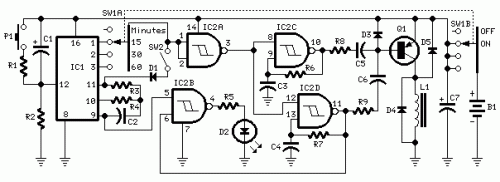
Circuit diagram
Parts:
- R1,R5 1K 1/4W Resistors
- R2 10K 1/4W Resistor
- R3,R6 10M 1/4W Resistors
- R4,R7 2M2 1/4W Resistors
- R8,R9 4K7 1/4W Resistors
- C1,C7 47µF 25V Electrolytic Capacitors
- C2 100nF 63V Polyester Capacitor
- C3,C4 330nF 63V Polyester Capacitors
- C5,C6 15nF 63V Polyester Capacitors
- D1,D3,D4,D5 1N4148 75V 150mA Diodes
- D2 LED (any type) (see Notes)
- IC1 4060 14 stage ripple counter and oscillator IC – This integrated circuit implements a 14-stage ripple counter and oscillator, generating precise timing signals for controlling the device's functionality.
- IC2 4093 Quad 2 input Schmitt NAND Gate IC – This integrated circuit comprises four independent Schmitt trigger NAND gate blocks, providing versatile logic gate functionality for the circuit’s control and timing functions.
- Q1 BC327 45V 800mA PNP Transistor – This transistor serves as a switching element, amplifying and controlling the current flow in the Radiator coil, facilitating its operation.
- L1 Radiator coil (see Notes) – The coil is constructed by winding 600 turns of 0.2 mm enameled wire around a 6 mm diameter, 40 mm long steel bolt, enhancing electromagnetic field generation.
- P1 SPST Pushbutton – This push button provides a manual reset mechanism for the device’s timing circuit.
- SW1 2 poles 4 ways rotary switch – This rotary switch offers selectable operation times of 15, 30, or 60 minutes.
- SW2 SPST Slider Switch – This slider switch allows selection between Stop and Alternate mode operation.
- B1 9V PP3 Battery – The PP3 battery provides the necessary power to operate the circuit.
- Clip for PP3 Battery – This clip secures the battery to the circuit board.
Features:
- Generates a natural electromagnetic-field
- Facilitates easier falling asleep
- Induces prolonged and restful sleep without the use of medications
- Offers no adverse side effects
Device purpose:
Many individuals have reported improved sleep quality when utilizing this device in natural settings, such as beneath a tent or within a wooden hut. This observation stems not only from the healthy atmospheric conditions but also from our inherent capacity to perceive natural Earth’s geomagnetic fields. The circuit replicates these geomagnetic fields, allowing for their perception, which in turn promotes an ideal environment for tranquil sleep. (N.B. The core ideas behind this circuit originate from German scientific papers).
Use:
Select a desired timing option via the rotary switch SW1, choosing from 15, 30, or 60 minutes of operation. Select “Stop” or “Alternate” mode operation utilizing the slider switch SW2. With SW2 closed (Stop mode operation), the electromagnetic radiation ceases automatically after the pre-determined time elapses. With SW2 opened (Alternate mode operation), the device operates for the preset duration, then pauses for the same period, creating a continuous cycle. Place the unit under the pillow and sleep soundly. To reset a cycle, press the P1 push button.
Circuit operation:
IC2 and IC2D generate two square waves at approximately 1.2 Hz and 5 Hz, respectively. These waveforms are converted into 60µS pulses at the same frequencies by means of C5 and C6, and the pulses are mixed at the base of Q1. This transistor controls the current flowing through the Radiator coil, employing a scalar series of 60µS pulses with a 9V amplitude. IC1, IC2A, and IC2B constitute the timing section. C1 and R2 provide an auto-reset function for IC1 upon power-on. The internal oscillator of IC1 drives the 14-stage ripple counter, and after roughly 15 minutes, the output pin 1 goes high. Pin 3 of IC2A goes low, thereby stopping the oscillation of IC2 and IC2D. If SW2 is left open (Alternate mode operation), after 15 minutes, pin 1 of IC1 goes low, pin 3 of IC2A goes high, and the oscillators are re-enabled. If SW2 is closed (Stop mode operation), the initial time output pin 1 of IC1 goes high, disabling the internal oscillator via D1. Therefore, the circuit remains inactive until a reset pulse is applied to pin 12 by means of P1 or when the entire device is powered off and then restarted. The same process occurs when SW1 is switched on for 30 or 60 minutes, modifying the operating time. IC2B drives the pilot LED D2, which operates in three modes: it flashes quickly and seemingly randomly when the Radiator coil is driven, it flashes slowly and regularly when the Radiator coil is paused during Alternate mode operation, and it is off when the circuit auto-stops (Stop mode operation).
Notes:
- L1 is obtained by winding 600 turns of 0.2 mm enameled wire on a 6 mm diameter, 40 mm long steel bolt. Secure the winding with insulating tape.
- Mean current draw is approximately 7mA, decreasing to less than 4mA during pauses when in Alternate mode operation.
- Battery life can be substantially extended by omitting LED D2 and its associated resistor R5.
- Use a plastic box to enclose the circuit; metal cases can severely limit electromagnetic radiation.
circuit from http://www.redcircuits.com/
