Build a Visual Doorbell: Circuit Diagram & "Please Wait" Illumination
Description:
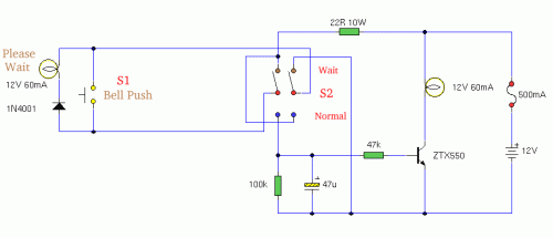
This circuit provides a delayed visual cue when a doorbell button is activated. Furthermore, a DPDT switch, controllable from within the residence, can activate a lamp positioned near the doorbell button. This lamp can display the phrase "Please Wait" for individuals with mobility impairments.
Circuit diagram
Notes:
The circuit employs conventional two-wire doorbell wiring or loudspeaker cable. Alongside the doorbell button, S1 incorporates a 1N4001 diode and a 12-volt, 60-mA bulb. The bulb is discretionary; it can benefit individuals who react slowly to the doorbell. By simply toggling a switch indoors, the bulb will illuminate a sign indicating "Please Wait" adjacent to the doorbell or near it. The double-pole double-throw switch directs the doorbell power to the lamp. The 22-ohm resistor is present to limit current flow if the doorbell button, S1, is pressed while the lamp is active. This resistor must be rated at 10 watts. A 0.5-amp fuse safeguards against short circuits.
When S2 is in the brown contact position (as depicted), the remote doorbell lamp will become illuminated. Conversely, when positioned in the blue contact location, this is the normal configuration, and the lamp within the house will light up. Switch S1 charges the 47u capacitor and activates the transistor, which then illuminates the lamp. Given that a doorbell button is only pressed briefly, the charge on the capacitor gradually diminishes, leading to the lamp remaining lit for several seconds. If a longer duration of illumination is desired, the value of the capacitor may be increased.
circuit from http://www.zen22142.zen.co.uk/
