Build Your 120V Inverter: A 1KW Power Solution
Description
Do you desire the ability to operate a television, audio system, or other appliance during road trips or camping excursions? This device, an inverter, offers a solution to that need. It converts 12 VDC into 120 VAC. The output power is determined by the transistors utilized for Q1 and Q2, as well as the size of the transformer designated as T1. The inverter can be configured to supply a range of power from 1 to 1000 (1 KW) watts.
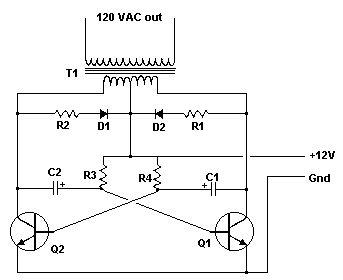
Circuit diagram
Parts:
- C1, C2 68 uf, 25 V Tantalum Capacitor
- R1, R2 10 Ohm, 5 Watt Resistor
- R3, R4 180 Ohm, 1 Watt Resistor
- D1, D2 HEP 154 Silicon Diode
- Q1, Q2 2N3055 NPN Transistor (see "Notes")
- T1 24V, Center Tapped Transformer (see "Notes")
- MISC Wire, Case, Receptical (For Output)
Notes:
- Q1 and Q2, alongside T1, significantly affect the wattage the inverter can deliver. With Q1, Q2 = 2N3055 and T1 = 15 A, the inverter can provide approximately 300 watts. Substituting larger transformers and more robust transistors for T1, Q1, and Q2 will increase the power output.
- The most straightforward and economical method for obtaining a large T1 involves re-winding an old microwave transformer. These transformers are typically rated at around 1KW and are well-suited for this purpose. Visit a local electronics repair shop and explore the dumpster until you locate the largest microwave you can find. A larger microwave generally corresponds to a bigger transformer. Carefully remove the transformer, paying close attention to avoid contact with the residual high-voltage capacitor that might still hold a charge. If desired, you can test the transformer; however, they are generally still functional. Next, remove the original 2000 V secondary winding, taking care not to damage the primary. Maintain the integrity of the primary winding. Proceed to wind 12 turns of wire, creating a center tap, followed by an additional 12 turns. The wire gauge should be selected according to the anticipated current requirements of the transformer. Enamel-coated magnet wire is an excellent choice for this application. Secure the windings with tape. This completes the modification. Remember to utilize high-current transistors for Q1 and Q2. The 2N3055 transistors listed in the parts list can only handle a maximum of 15 amps each.
- It’s important to acknowledge that when operating at higher wattages, this circuit draws substantial amounts of current. Avoid depleting your battery completely :-).
- Given that this circuit generates 120 VAC, it’s essential to incorporate a fuse and construct the project within a protective enclosure.
- The use of tantalum capacitors for C1 and C2 is mandatory. Regular electrolytic capacitors are prone to overheating and potential explosions. And yes, 68uF is the correct capacitance value. There are no permissible substitutions.
- This circuit can be challenging to implement successfully. Variations in transformers, transistor substitutions, or any deviations from the specifications outlined on this page may lead to malfunction.
circuit from http://www.aaroncake.net/
