12V to 220Vac 50W Converter Schematic
Description
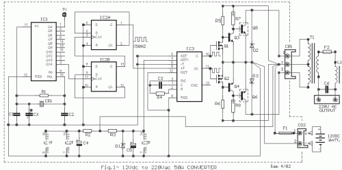
In numerous instances, a 220VAC voltage is required, particularly in scenarios where it does not exist, to power various small appliances. Figure 1 illustrates a voltage conversion circuit transforming 12VDC to 220VAC, delivering approximately 50W of output power. The circuit’s construction involves an oscillator around IC1, a divider IC2, an unstable multivibrator IC3, which generates a symmetrical square output signal at a frequency of 50HZ, followed by a buffer stage utilizing FETs Q1-2, a drive stage consisting of Q3-4, and a power stage comprised of Q4-5, all of which are mounted on heat sinks. The diodes D2-3 protect the power transistors from voltage spikes produced by the transformer T1. Transformer T1 is a standard power transformer with an intermediate reception, connected to the contacts of CO1. For the intended application, T1 is installed in reverse, utilizing its secondary winding as the primary, with the intermediate reception connected to the positive terminal of the 12V battery. The remaining two contacts are connected to the emitters of Q5-6, which are alternately connected to ground, determined by the rhythms produced by outputs 10 and 11 of IC3. This configuration ensures that AC current flows through the primary while generating a 220V AC square voltage in the secondary. The utilization of a crystalline oscillator ensures a stable reference frequency of 50HZ, employing a standard crystal (CR1). To enhance precision, a variable capacitor (Cx) is parallelled with C1, enabling frequency regulation to achieve a frequency of 204.8 KHZ at point P1. It is evident that the output voltage in the absence of a load exceeds the voltage with a load. The output voltage is also dependent on the battery’s output voltage. For a 14V battery voltage, the output voltage increases by 10% compared to the battery’s 12V. When operating in a load range of 40 to 60W, a transformer 2X9V can be utilized. Various output values for a 12V battery and a 2X10V transformer are shown in Table 1.Table 1. Output Power Output Voltage AC
- 0W - 238V
- 25W - 220V
- 40W - 202V
- 75W - 170V
- 100W - 150V
Circuit diagram
Part List
- R1=10Mohms
- R2=100ohms
- R3=1.2Kohms
- R4=560Kohms
- R5-6=2.2Kohms
- R7-8=56 ohms 5W
- CX=22pF trimmed capacitor
- C1-2=22pF ceramic
- C3=8.2nF 100V MKT
- C4=10uF 16V
- C5=47uF 16V
- C6=470nF 400V
- D1=5V6 0.4W
- D2-3=47V 1W
- Q1-2=BS170
- Q3-4=BD139
- Q5-6=BD249
- IC1=4060
- IC2=4013
- IC3=4047
- CR1=3.2768 MHZ crystal
- T1=220Vac/2X10V 2X2.2A *see text
- F1=5A Fuse
- F2=0.25A Fuse
- L1=1H smoothing choke
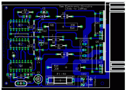
Fig.2- 12Vdc to 220Vac converter PCB component (top) side.
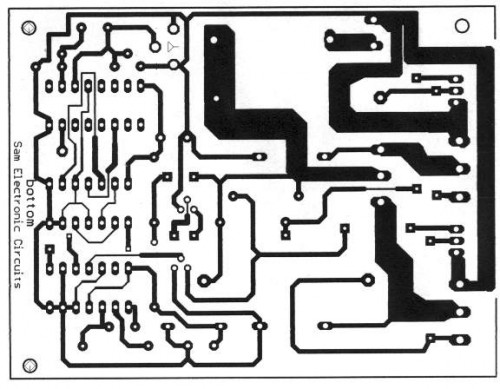
Fig.3- 12Vdc to 220Vac converter PCB bottom side.
In the Fig.2, exists the printed circuit with the layout of material [ top side ] and in the Fig.3 exist PCB from the bottom side (brass side).


