Boost Your Video Clarity: A 3-Transistor Circuit
Description
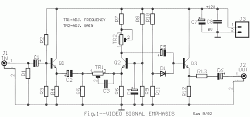
This circuit enables selective amplification of high-frequency picture signals [Video], resulting in enhanced image clarity compared to conventional approaches. The circuit should be positioned between a video source and the Scart or video input connector of a television receiver. The design is straightforward, relying on three transistors. The initial stage, utilizing TR1, operates as an input isolator and impedance adapter. The second stage, employing TR2 in a common-base configuration, determines the amplification gain. Furthermore, the combination of TR1, R6, and C3 shapes the frequency response. The final stage, utilizing TR2, functions as an output buffer and a 75-ohm line driver. The TR2 value must be carefully adjusted to achieve an output voltage of 1Vp-p when connected to a 75-ohm load. This circuit operates reliably with a stabilized 12Volts – 50mA power supply.
More about components
Integrated circuits play a crucial role in this circuit's functionality. Specifically, the BC547 transistors (Q1, Q2, and Q3) are fundamental components. These are small, self-contained semiconductor devices that integrate multiple active components, such as transistors, resistors, and capacitors, onto a single chip. BC547 transistors are commonly used in audio and low-power applications due to their general-purpose nature and relatively low cost. Their versatility allows them to be employed in various stages of amplification, providing suitable gain and switching characteristics.
Circuit diagram
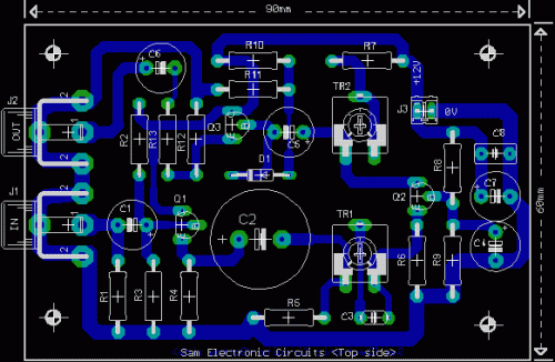
Part List
- R1=82ohm
- R2=5.6Kohm
- R3-9-11=2.7Kohm
- R4=330ohm
- R5=220ohm
- R6=470ohm
- R7=270ohm
- R8=12Kohm
- R10=2.2Kohm
- R12=180ohm
- R13=68ohm
- C1-4-5=100uF 16V
- C2=2200uF 16V
- C3=470pF ceramic
- C6=470uF 16V
- C7=220uF 16V
- C8=100nF 100V MKT
- TR1=250ohm trimmer
- TR2=500ohm trimmer
- D1=1N4148
- Q1-2-3=BC547
- J1-2=Female RCA jack
- J3=2pin connector 2.54mm step

