- Build Your Own Digital Lock: A 4017 Circuit Project
- Build Your Own 147 Electronic Security Door Lock Circuit
- Build Your 7-Digit Security Door Circuit: A Detailed Guide
- Build Your Secure 4-Digit Door Release Circuit Diagram
- Build Your 12-Keypad Circuit Diagram Now!
- Build a 4-Digit Keypad Switch Circuit with a Secure Code
Build Your 12-Keypad Circuit Diagram Now!
Description
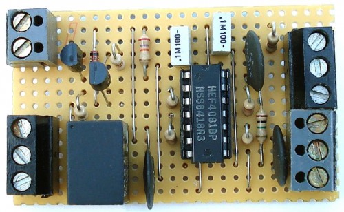
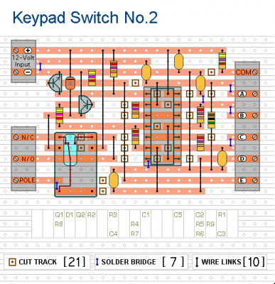
The circuit is depicted utilizing a 12-volt power source, however, it exhibits functionality within a range of 5 to 15 volts. Selection of a relay appropriately rated for the desired supply voltage is necessary. Substitution of the SPCO/SPDT relay with a multi-pole relay is recommended, contingent upon the specific requirements of the application.
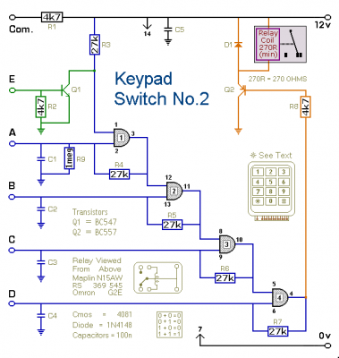
Schematic Diagram
IMPORTANT!!!
It is imperative not to employ the internal relay for switching mains voltage. The board’s design lacks sufficient insulation between the relay contacts and the low-voltage components. If mains voltage switching is required, a relay of adequate specifications should be installed in a safe location – Away From The Board.
Notes
Select the desired four keys to be utilized as the Code, and connect them to “A B C & D”. Wire the common terminal to R1, and connect the remaining keys to “E”. The circuit will activate upon relay energization. De-energizing requires entering the specified code. Re-energization is achieved by pressing any of the keys linked to “E”.
To reverse the operational behavior of the circuit, replace Q2 with a BC547. With an NPN transistor in this configuration, the circuit will activate with the relay de-energized. To energize it, the code must be entered. To deactivate it again, pressing any of the keys connected to “E” is sufficient.
Any keys not connected to “A B C & D” are connected to the base of Q1. When one of these “Incorrect” keys is pressed, Q1 pulls pin 1 low, and the code entry sequence fails. Should an error occur during code entry, the process can be restarted.
The Keypad must be of the type featuring a common terminal alongside a dedicated connection for each individual key. For a 12-key pad, identify 13 terminals. A matrix type with 7 or 8 terminals will not function correctly. A 12-key pad possesses eight “Incorrect” keys linked to “E”. For a more secure code, utilize a larger keypad with an increased number of “Incorrect” keys.


