- Build Your Own Digital Lock: A 4017 Circuit Project
- Build Your Own 147 Electronic Security Door Lock Circuit
- Build Your 7-Digit Security Door Circuit: A Detailed Guide
- Build Your Secure 4-Digit Door Release Circuit Diagram
- Build Your 12-Keypad Circuit Diagram Now!
- Build a 4-Digit Keypad Switch Circuit with a Secure Code
Build Your 7-Digit Security Door Circuit: A Detailed Guide
Circuit
Description
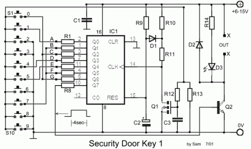
This circuit represents a basic security lock system employing a seven-digit code. Careful monitoring is required during key presses as they shape the code, and an immediate delay isn't present. Upon correctly inputting the code, the output Q7 is activated for approximately 4 seconds, controlling the transistor Q2, which subsequently drives a relay to unlock the door, or any other connected circuit. An LED, designated D1, provides a visual indication of the activation. The established circuit code is 1704570, though modifications to the connections between the outputs of IC1 and the switches can alter this code.
Integrated Circuit Details
IC1: 4022
The 4022 is a versatile decade counter integrated circuit. This component is frequently utilized for sequential control applications, such as clock generation, countdown timers, and simple digital displays. Its primary function is to count from 0 to 99, providing a series of outputs that can be used to implement various timing and counting functions within the security lock. The IC is a monolithic CMOS integrated circuit and it operates on a low voltage power supply. The 4022 is commonly found in hobbyist electronic projects due to its ease of use and relatively low cost. Its digital output can be precisely controlled and used in a variety of circuits. The IC has 10 output pins and 3 input pins. It is also very popular due to the availability of many datasheets and examples on the internet.
Part List
- R1-7=4.7Kohm
- R8=15Kohm
- R9=1Mohm
- R10-13=10Kohm
- R11=100ohm
- R12=220Kohm
- R14=1.2Kohm
- C1-3=100nF 100V
- C2=4.7uF 25V
- D1-2=1N4148
- D3=RED LED 3mm
- IC1=4022
- Q1=BS170
- Q2=BD679
- S1-10=Push button or keyboard
WARNING: This circuit involves electrical components and may pose a risk of electric shock. Exercise caution and ensure proper safety measures are followed during assembly and operation. This circuit diagram is provided as-is, and the author assumes no responsibility for any damage or injury resulting from its use.
Source: [url]https://www.example.com/circuit-diagram[/url]
