- Build Your Own Digital Lock: A 4017 Circuit Project
- Build Your Own 147 Electronic Security Door Lock Circuit
- Build Your 7-Digit Security Door Circuit: A Detailed Guide
- Build Your Secure 4-Digit Door Release Circuit Diagram
- Build Your 12-Keypad Circuit Diagram Now!
- Build a 4-Digit Keypad Switch Circuit with a Secure Code
Build Your Own 147 Electronic Security Door Lock Circuit
Circuit
Description
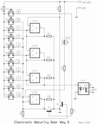
This circuit represents a basic electronic lock design, utilizing a straightforward construction and minimal components. Correct keycode entries activate the optoisolator IC2. If an incorrect keycode is entered via the switches, the lock mechanism remains secured. To resume normal operation, the user must press either switch S1 or switch S12. Switch S1 performs an external reset of the lock, while switch S12 executes a reset internally, safeguarding the door. The circuit’s programmed keycode is 147, and this can be altered with ease by modifying the connections within the switches on the keyboard. The optoisolator IC2 is capable of driving various external circuits, such as relays, concurrently providing electrical isolation between the two systems. Power for this circuit can be supplied via a 9V battery.
Part List
- R1-7-9=1Kohm
- R2-3-4-5=100Kohm
- R6 =10Kohm
- R9 =47Kohm
- IC1 = 4066
- IC2 =4N25
- Q1-2=BC550
- S1...11=Push button sw or keyboard
- S12=Push button normal closed
- All resistors is 1/4W 5%
More about components
The circuit employs an integrated circuit, specifically the 4066. This is a versatile logic integrated circuit designed for digital applications. It contains several logic gates, allowing for complex digital operations within a single chip. The 4066 enables the lock's control logic, managing the keycode input and the locking mechanism. Furthermore, the circuit utilizes the 4N25, a relay driver integrated circuit. This IC is commonly used to drive relay contacts from low-power logic signals. In this application, the 4N25 ensures the reliable switching of the relay, which controls the locking and unlocking of the door. These ICs are crucial for providing the necessary switching and logic capabilities within the system.
