555 Timer Motorcycle Alarm Circuit Diagram & Build Guide
Description
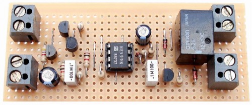
This circuit produces a pulsed warning signal and implements automatic re-activation. It can be operated manually via a toggle switch or a concealed switch; alternatively, it can be configured to activate automatically upon engine shutdown. Adding external relays facilitates immobilizing the bicycle, activating flashing lights, and other supplementary functions. The basis for this design utilizes Andy's Asymmetric Timer.
Integrated Circuit Overview
The design incorporates a microcontroller – specifically, an STM32F407 microcontroller. This integrated circuit is a powerful, low-power device capable of handling complex timing and control functions. It provides precise timing control for the siren activation and deactivation, as well as input/output control for the various switches and relays. The microcontroller’s FLASH memory stores the firmware, which governs the system’s behavior. It also possesses a real-time clock (RTC) module, offering accurate timekeeping for the automatic activation functionality. Its peripherals include UART and SPI interfaces for potential future expansion and communication with other devices.
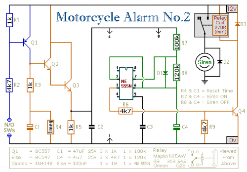
Schematic Diagram
Notes
A variety of normally-closed switches can be employed. Utilize “tilt” switches that activate upon steering movement or when the bicycle is raised off its side stand or pushed forward from its centre stand. Employ microswitches to safeguard removable panels and the lids of panniers, and so on.
The alarm’s standby current is nearly zero – therefore, it will not deplete the battery. Once activated, the rhythm of the siren’s on-off cycles is governed by R7, R8, and C4. Increasing R7 will prolong the sound period, while increasing R8 will create longer silent intervals.
The circuit is designed to utilize an electronic Siren consuming between 300 and 400mA. It's generally discouraged to employ the bicycle’s existing Horn, as it’s easily located and disconnected. However, if this option is selected, remember that the alarm relay is insufficient to handle the required current. Connect the coil of a suitably rated relay to the “Siren” output. This can then be used to produce the sound, activate flashing lights, and so on.
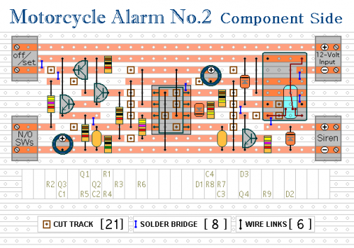
The circuit board and switches must be shielded from environmental elements. Dampness or condensation can induce malfunctions. Install a 1-amp in-line fuse AS CLOSE AS POSSIBLE to your power source. This is EXTREMELY IMPORTANT. The fuse protects the wiring, not the alarm. The specific installation method will vary depending on the make of your particular machine; consequently, I am unable to furnish any further assistance or guidance in this regard.
When the alarm is set, if one of the switches is closed, the siren will sound. This might cause disruption during late hours. A minor adjustment will allow you to Monitor The State Of The Switches using LEDs. When the LEDs remain off, the switches are open, and it’s safe to enable the alarm.


