Build Simple Motorcycle Alarms with Relays
Description
These are two simple relay-based alarm systems, easily constructed for use in protecting a motorcycle – though their applications extend far beyond. If you employ 6-volt coil relays, they will safeguard your "Classic Bike." Both alarms are remarkably compact, occupying approximately half a cubic inch – 8 cubic centimeters. The standby current is zero, ensuring they won't deplete your battery.
Circuit No.5
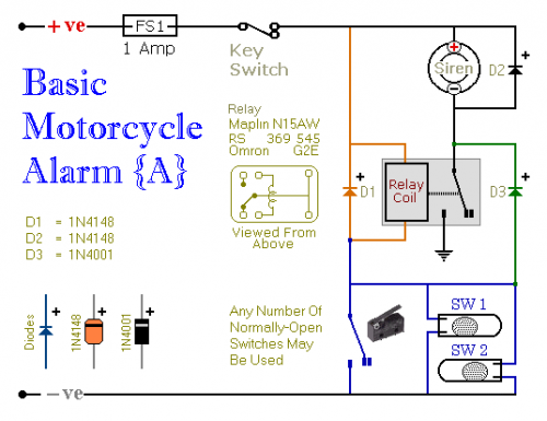
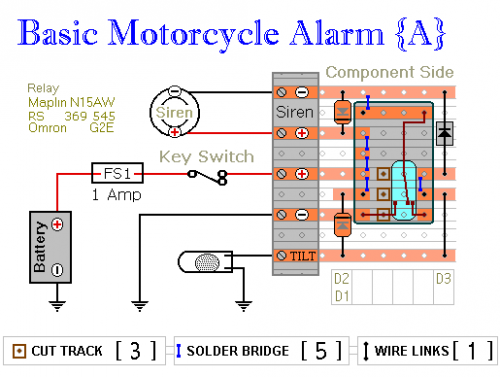
Circuit Number Five utilizes a SPCO/SPDT relay, but a SPST relay is sufficient. For the veroboard layout provided, a relay of the specified type is necessary. However, construction is possible using any available relay style.
Multiple normally-open switches can be incorporated. Position the mercury switches to activate when the steering is moved, when the bike is lifted off its side-stand, or when pushed forward off its centre-stand. Micro-switches can be employed to protect removable panels and the lids of panniers. When any trigger-switch is closed, the relay energizes, and the siren sounds.
The desired behavior can be selected. When built as shown, the siren continues to sound until manually deactivated or until the battery is exhausted. However, omitting D3 will cause the siren to immediately cease sound upon re-opening the trigger-switch.
In situations where you're within earshot of the machine, the former configuration is preferable, allowing for immediate manual silencing. If you are going to be away from your bike for an extended period and wish to avoid causing a disturbance, the latter configuration is more suitable. Adding a SPST switch in place of D3 enables selection of the behavior appropriate to the circumstances at any given time.
Relay coils and certain sounders can generate high reverse-voltage spikes that may damage sensitive electronic components. D1 and D2 are strategically placed to short-circuit these spikes, preventing any potential harm. While the alarm circuit itself is protected, the potential for damage from other connected electronic equipment to the same power supply necessitates these diodes as a preventative measure. If you are assured that no other equipment might be vulnerable to such spikes, the diodes can be omitted.
Circuit No.6
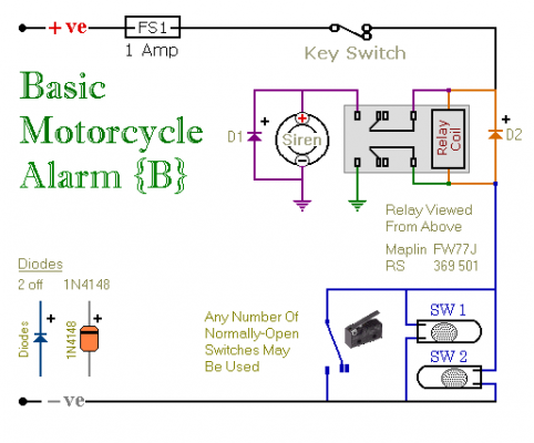
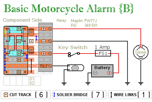
Circuit Number Six employs a DPCO/DPDT relay, though a DPST relay is adequate. For the veroboard layout, utilize the specified relay type. However, construction is possible with any relay style.
Multiple normally-open switches may be used. Position the mercury switches to activate when the steering is moved, when the bike is lifted off its side-stand, or when pushed forward off its centre-stand. Micro-switches can be used to protect removable panels and the lids of panniers. When any trigger-switch is closed, the relay energizes and the siren sounds.
The desired behavior can be selected. When built as shown, the siren continues to sound until manually deactivated or until the battery is exhausted. However, omitting the (yellow) solder-bridge in the top left-hand corner of the diagram will cause the siren to immediately cease sound upon re-opening the trigger-switch.
In situations where you’re within earshot of the machine, the former configuration is preferable, allowing for immediate manual silencing. If you are going to be away from your bike for an extended period and wish to avoid causing a disturbance, the latter configuration is more suitable. Connect a SPST switch in place of the (yellow) solder-bridge - and you can select the behaviour appropriate to the circumstances at any given time.
Relay coils and certain sounders can generate high reverse-voltage spikes that may damage sensitive electronic components. D1 and D2 are strategically placed to short-circuit these spikes, preventing any potential harm. While the alarm circuit itself is protected, the potential for damage from other connected electronic equipment to the same power supply necessitates these diodes as a preventative measure. If you are assured that no other equipment might be vulnerable to such spikes, the diodes can be omitted.
General Points
Regardless of the alarm chosen, the circuit board and switches must be protected from environmental elements. Dampness or condensation will cause damage. Without the terminal blocks, the board is small. Ideally, locate a siren with sufficient internal space to accommodate it. Incorporate a 1-amp in-line fuse as close as possible to the power source. This is Extremely Important. The fuse protects the wiring, not the circuit board. Rather than a key-switch, a hidden switch or a normally-closed contact relay can be employed. Wire the relay coil so that it's energized while the ignition is on. Then, when the ignition is switched off, the alarm will automatically reset.
When the alarms are not in operation, the circuits consume no current. This makes them valuable in situations where a readily available power supply is unavailable. Powered by dry batteries, with appropriately chosen relay and siren voltages, the alarms can be fitted almost anywhere.


