Simple Transistor Motorcycle Alarm Circuit Diagram
Description
This straightforward – easily constructed – transistor-based motorcycle alarm is designed to operate at 12 volts. However, by substituting a relay featuring a 6-volt coil – you can safeguard your “Classic Bike”. The circuit’s standby current is nearly zero – preventing battery drain.
Schematic Diagram
Notes
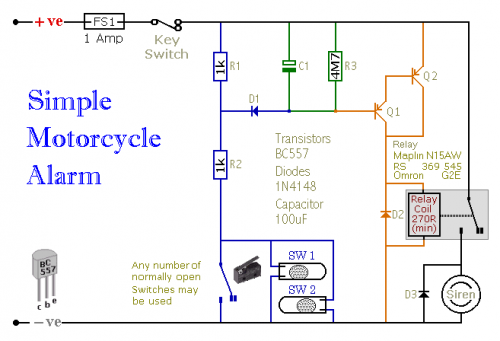
An indefinite number of normally-open switches may be employed. Position the mercury switches so that they activate when the handlebars are manipulated or when the motorcycle is elevated from its side stand or pushed forward from its center stand. Utilize micro-switches to protect removable panels and the lids of panniers, and so on. As long as at least one switch remains closed – the siren will trigger its sound.
Approximately one minute after all the switches are reopened – the alarm will automatically reset. The duration required for the deactivation process varies depending on the specific characteristics of the components you have utilized. You can customize the timing by adjusting the value of C1 and/or R3 to align with your particular needs.
The circuit is engineered to utilize an electronic Siren consuming between 300 and 400 milliamps. It's generally not advisable to leverage the motorcycle’s original Horn – as it's readily identifiable and easily disconnected. Nevertheless, should you opt to incorporate the Horn – bear in mind that the alarm relay is insufficiently rated to handle the requisite current. Connect the coil of a suitably sized relay to the Siren output – and employ its contacts to activate the horn.
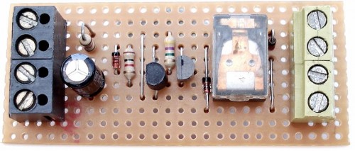
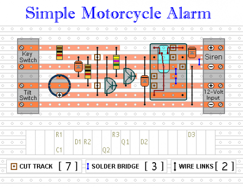
The circuit board and switches must be shielded from environmental elements. Moisture or condensation will induce malfunctions. Without the terminal blocks, the board is compact. Ideally, locate a siren possessing sufficient internal space to accommodate it. Install a 1-amp in-line fuse as close as achievable to the power source. This is Extremely Important. The fuse serves to protect the wiring – not the circuit board. Instead of employing a key-switch, you may use a concealed switch; or you could utilize the normally-closed contacts of a small relay. Wire the relay coil so that it’s powered while the ignition is active. Then, every time the ignition is deactivated – the alarm will automatically engage.
When the alarm is inactive, the circuit consumes almost no current. This characteristic renders it suitable for various applications. For example, powered by dry batteries and with the relay and siren voltages appropriately configured – it could be integrated into a computer or any other item susceptible to being carried away. The low standby current and automatic reset capability mean that for this kind of application, an external on/off switch may not be necessary.
When setting the alarm – if one of the switches is closed – the siren will emit its sound. This could cause disruption during late hours. A minor adjustment will permit you to Monitor The State Of The Switches employing LEDs. When the LEDs are all extinguished – the switches are all open – and it’s safe to activate the alarm.


