similar circuits
- Three Channel Audio Splitter Circuit Diagram & Build Guide
- Build a 500Hz-2Khz Notch Filter with 0.1uF & 1.5K Resistors
- Build Your 1700Hz Op-Amp Bandpass Filter Circuit
- Build Stunning 2nd Order Opamp Filters – Design Guide
- Craft a 300-3kHz Bandpass Filter Circuit Diagram
- Separate Stereo Bass: A Circuit for Clarity
- Variable High-Pass Filter: 20Hz to 200Hz Design
Build Stunning 2nd Order Opamp Filters – Design Guide
Description
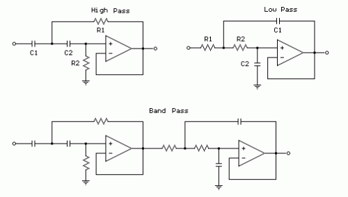
The illustrations beneath depict the utilization of operational amplifiers (opamps) within the design of second-order filters. Three distinct second-order filter types are presented: a low-pass filter, a high-pass filter, and a bandpass filter. These filters are engineered to diminish the amplitude of frequencies that lie outside their designated passband, with an attenuation rate of 12dB per octave or a voltage amplitude reduction of 1/4 for each octave of frequency deviation from the passband.
- The first-order low-pass cutoff frequency is calculated as 1/(2π*R*C)
- The 2nd order low or high pass cutoff frequency (-3dB point) is determined by the formula 1/2π(R1*R2*C1*C2)^.5
- For a 200 Hz cutoff frequency, values of R1=R2=7.95K and C1=C2=0.1uF are employed.
