- Three Channel Audio Splitter Circuit Diagram & Build Guide
- Build a 500Hz-2Khz Notch Filter with 0.1uF & 1.5K Resistors
- Build Your 1700Hz Op-Amp Bandpass Filter Circuit
- Build Stunning 2nd Order Opamp Filters – Design Guide
- Craft a 300-3kHz Bandpass Filter Circuit Diagram
- Separate Stereo Bass: A Circuit for Clarity
- Variable High-Pass Filter: 20Hz to 200Hz Design
Build Your 1700Hz Op-Amp Bandpass Filter Circuit
Description
A bandpass filter allows a specific range of frequencies to pass through while attenuating frequencies outside that range. The frequency range that is permitted to pass is known as the passband and extends from a point below the center frequency to a point above the center frequency, where the output voltage typically represents approximately 70% of its maximum value at the center frequency. These two points are not equally spaced above and below the center frequency, but they appear equally spaced when plotted on a logarithmic graph. The percentage change from the lower point to the center frequency will match the percentage change from the center frequency to the upper frequency limit, although the absolute difference will differ. This behavior is similar to the arrangement of keys on a musical keyboard, where each key is separated from the next by the same percentage change in frequency, despite the keys not being the same distance apart.
The bandwidth (BW) of the filter is defined as the difference between the upper and lower frequencies of the passband. A formula that relates the upper, lower, and center frequencies of the passband is as follows:
Center Frequency = Square Root of (Lower Frequency * Upper Frequency)
The quality factor, often denoted as ‘Q’ of the filter, is a measure of the separation between the upper and lower frequency limits and is calculated as (Center Frequency / BW). Consequently, as the passband narrows around the same center frequency, the Q factor increases. The quality factor represents the sharpness of the filter, or the rate at which the amplitude decreases as the input frequency moves away from the center frequency during the first octave. When the frequency is more than one octave away from the center frequency, the roll-off approaches 6 dB per octave, regardless of the Q value. Approximate roll-off rates for different Q values during a single octave change from the center frequency are as follows:
- Q = 1 = 6 dB
- Q = 5 = 18 dB
- Q = 10 = 24 dB
- Q = 50 = 40 dB
For a single operational amplifier (op-amp) bandpass filter with equal capacitor values, the Q factor must be greater than the square root of half the gain, so that a gain of 98 would require a Q factor of 7 or more.
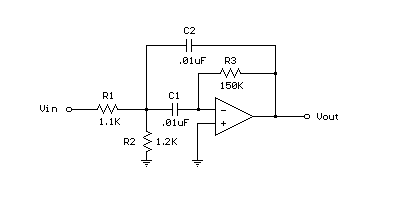
The example below displays a 1700 Hz bandpass filter with a Q of 8 and a gain of 65 at the center frequency (1700 Hz). Resistor values for the filter can be determined using the three formulas provided below. Both capacitor values must be identical for these formulas to apply, and they are chosen to be 0.01uF, a common value utilized at audio frequencies. This same filter is employed in the "Whistle On / Whistle Off" relay toggle circuit.
- R1 = Q / (G*C*2*Pi*F) = 8/(65 * .00000001 * 6.28 * 1700) = 1152 or 1.1K
- R2 = Q / ((2*Q^2)-G)*C*2*Pi*F) = 8/((128-65) * .00000001 * 6.28 * 1700) = 1189 or 1.2K
- R3 = (2*Q) / (C*2*Pi*F) = 16 / (.00000001 * 6.28 * 1700) = 150K
Operational Amplifier (Op-Amp) Details
Operational amplifiers, often abbreviated as op-amps, are integrated circuits that provide high gain and are fundamental building blocks in countless electronic circuits. They are characterized by their extremely high input impedance (essentially infinite) and very low output impedance, allowing them to drive loads with minimal signal loss. Op-amps are utilized in a vast array of applications, including amplifiers, filters, oscillators, and data converters. The key features of an op-amp are its differential input, which amplifies the difference between the two inputs, and its high gain, which provides substantial amplification of the signal. The specific characteristics, such as input offset voltage and bandwidth, vary significantly depending on the particular op-amp model and its intended application. The use of op-amps in bandpass filters is particularly common due to their ability to precisely shape the frequency response of the filter. The output of an op-amp in a bandpass configuration is often fed into a load, such as a speaker or another amplifier stage. The op-amp itself typically operates in its open-loop configuration, where its gain is very high and the output voltage is largely determined by the input signal and the filter components. Typical op-amps used in filter design include the LM358 and TL072, although numerous other models are available.
