- VU Meter Sound Level Circuit
- Build Your Own 8-LED VU Meter Circuit – Power Levels Explained
- VU Meter 5: UAA180 Circuit Diagram & Build Guide
- Build Your Own Audio Analyzer Circuit Diagram
- Build Your Own VU Meter: LM3915 Circuit Diagram
- Build Your 10-LED Level Indicator Circuit (LM3915, TL071)
- VU Meter Circuit: Build Your 7.8V Level Indicator
- Build Your Own VU Meter: A 13-LED Circuit Design
- 74C14 Peak Indicator Circuit: Build Your Audio Level Meter
- Build Your 4dB Peak Indicator Circuit Diagram
- Three Level Audio Power Indicator Circuit Design
- Build Your Own LM3915 Sound Level Meter Circuit
Build Your Own VU Meter: LM3915 Circuit Diagram
Description
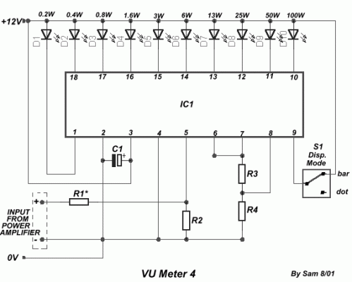
The circuit is connected in parallel with the output of the power amplifier and provides signal level measurement from the amplifier’s output. Adjusting the resistance value, R1, within the input circuit allows for adaptation of the power reading measured by the loudspeaker resistance utilized.
LM3915
The LM3915 is a versatile operational amplifier (op-amp) commonly employed in various electronic applications. This integrated circuit offers high gain, low input bias current, and excellent stability, making it suitable for amplifying weak signals, building instrumentation, and implementing precision circuits. It typically features three operational amplifier stages, offering multiple gain options and flexibility in circuit design. It is a popular choice for audio amplifiers, sensors, and general-purpose analog circuits.
Circuit diagram
Part list
- R1=10Kohm for 4ohm
- R1=18ohm for 8ohm
- R2=10Kohm
- R3=390ohm
- R4=2.7Kohm
- C1=2.2uF 25V
- D1-10=LED
- S1=mini switch
- IC1=LM3915
