- VU Meter Sound Level Circuit
- Build Your Own 8-LED VU Meter Circuit – Power Levels Explained
- VU Meter 5: UAA180 Circuit Diagram & Build Guide
- Build Your Own Audio Analyzer Circuit Diagram
- Build Your Own VU Meter: LM3915 Circuit Diagram
- Build Your 10-LED Level Indicator Circuit (LM3915, TL071)
- VU Meter Circuit: Build Your 7.8V Level Indicator
- Build Your Own VU Meter: A 13-LED Circuit Design
- 74C14 Peak Indicator Circuit: Build Your Audio Level Meter
- Build Your 4dB Peak Indicator Circuit Diagram
- Three Level Audio Power Indicator Circuit Design
- Build Your Own LM3915 Sound Level Meter Circuit
Build Your 4dB Peak Indicator Circuit Diagram
Description
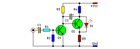
This straightforward circuit acts as a peak detector for audio signals, signaling the crests of musical waveforms. Whenever the signal's amplitude surpasses a level of +4dB, the red LED (D1) illuminates. This design is applicable across various audio applications, including console channels, final amplification stages, and similar scenarios where peak detection is required. The circuit’s initial signal levels are calibrated to commence at amplitudes exceeding +4 dB (1.25V rms) due to the use of a trimmer capacitor prior to C1 for signal adjustment.
Circuit Diagram:
Parts:
- R1 = 10K
- R2 = 1.2K
- R3 = 220K
- R4 = 4.7K
- R5 = 4.7K
- C1 = 47uF-25V
- C2 = 2.2uF-25V
- Q1 = BC550C
- Q2 = BC550C
- D1 = Red LED
Integrated Circuits Description
The circuit employs two BC550C transistors, commonly utilized NPN bipolar junction transistors. These transistors act as switching elements, responding to the input signal and controlling the LED’s current flow. The BC550C is a general-purpose transistor known for its robustness and reliability, frequently found in various electronic circuits due to its ease of use and relatively high current gain. Its low cost further contributes to its widespread adoption in both amateur and professional electronics projects.
Notes:
- It can be assembled on a general purpose PCB.
- It can be powered from a 12V-15V regulated power supply.
