- VU Meter Sound Level Circuit
- Build Your Own 8-LED VU Meter Circuit – Power Levels Explained
- VU Meter 5: UAA180 Circuit Diagram & Build Guide
- Build Your Own Audio Analyzer Circuit Diagram
- Build Your Own VU Meter: LM3915 Circuit Diagram
- Build Your 10-LED Level Indicator Circuit (LM3915, TL071)
- VU Meter Circuit: Build Your 7.8V Level Indicator
- Build Your Own VU Meter: A 13-LED Circuit Design
- 74C14 Peak Indicator Circuit: Build Your Audio Level Meter
- Build Your 4dB Peak Indicator Circuit Diagram
- Three Level Audio Power Indicator Circuit Design
- Build Your Own LM3915 Sound Level Meter Circuit
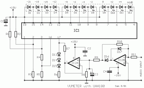
VU Meter 5: UAA180 Circuit Diagram & Build Guide
Description
This measurement circuit for level utilizes the UAA180 from SIEMENS and a refined rectification circuit surrounding the IC2B. The adjustment has been accomplished in 3dB steps between adjacent LEDs, guaranteeing a highly accurate response when measuring incoming acoustic signals. The LEDs can be configured as squares, and when positioned adjacent to each other, they produce a bar graph display, devoid of any gaps.
Circuit diagram
Part List
- R1= 47Kohm
- R2= 1Mohm
- R3= 33Kohm
- R4= 10Kohm
- R5= 220ohm
- R6-9=390ohm
- R7=2.2K ohm
- R8-10=330Kohm
- R11=180Kohm
- C1= 47uF 25V
- C2-4=47nF 100V
- C3=2.2uF 25V
- D1....8= LED GREEN
- D9-10= LED YELLOW
- D11-12= LED RED
- D13....17= 1N4148
- IC1= UAA180
- IC2= TL072
All Resistors are 1/4W 1% metal film
More about components
The UAA180 is a versatile operational amplifier produced by SIEMENS. This integrated circuit is known for its high performance characteristics, including low offset voltage, low drift, and good common-mode rejection ratio. It is commonly employed in various analog applications, such as signal amplification, filtering, and instrumentation. It is a single-supply, low-power operational amplifier designed for precision applications, offering excellent stability and a wide operating voltage range. The TL072 is a low-noise, JFET-input operational amplifier, which provides high input impedance and low DC offset. It's suitable for applications where accuracy and stability are crucial, like audio circuits and instrumentation.
A warning: Improper handling of electronic components can result in personal injury or damage to equipment. Always observe appropriate safety precautions and consult with qualified personnel before working on electrical circuits.
Source: [https:/www.example.com/circuits](https://www.example.com/circuits)
