- Car Headlights Timer Circuit: Build Your 1min 30sec Delay
- Build Your Motor Bike Headlight Controller Circuit
- Build Your Own 30V LED Bike Light Circuit
- Build Your 12V Headlight Reminder Circuit with a Buzzer
- Fog Light Circuit: Trailer Connection & Relay Control
- Build a 13-Way Optocoupler Fog Lamp Sensor Circuit
- Car Bulb Flasher Circuit Diagram: 12V 21W Flashing Lights
- Automobile Fader Circuit Diagram: 700Hz & 5s Fade
- DIY Headlight Timer Circuit: 1 Minute Delay Build
- Automatic Headlight Brightness Switch – Build Your Smart Circuit
DIY Headlight Timer Circuit: 1 Minute Delay Build
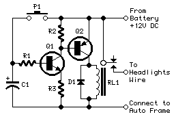
This device represents a straightforward circuit design, facilitating a timer function for vehicle headlights, enabling operation for approximately one minute and thirty seconds, for instance, during access to dimly lit areas, without requiring a return to manually switch off the lights.
A relatively simple circuit arrangement is employed here.
Circuit Diagram
Components:
- R1 4.7KΩ 1/4W Resistor
- R2, R3 1KΩ 1/4W Resistors
- C1 100µF 25V Electrolytic Capacitor (See Specifications)
- D1 1N4002 100V 1A Diode
- Q1 BC547 45V 100mA NPN Transistor
- Q2 BC327 45V 800mA PNP Transistor
- P1 SPST Pushbutton
- RL1 Relay with SPDT 10A Minimum Switch
- Coil Voltage 12V. Coil Resistance 150-600 Ohms
Comments:
This particular circuit is a basic timer, allowing for the sustained operation of vehicle headlights for approximately one minute and thirty seconds, for example, when navigating darker locations, eliminating the need for a return trip to manually switch them off.
Circuit Operation:
Activating the pushbutton (P1) initiates the charging of capacitor C1, drawing power from the vehicle’s full 12V battery supply. Consequently, transistor Q1 is driven hard-on, subsequently activating transistor Q2 and its associated Relay load. The vehicle’s headlights are thus energized through the Relay contact, wired in parallel to the standard vehicle headlights switch. Relay RL1 remains engaged until capacitor C1 is nearly fully discharged, indicated by a voltage drop below approximately 0.7V. The timing duration of the circuit is determined by the values of components C1 and R1, and was set to approximately one minute and thirty seconds. Variations in the tolerance of electrolytic capacitors used for C1 will cause this delay to fluctuate between roughly one minute and thirty seconds and one minute and fifty seconds. An alternative implementation involves utilizing the interior lamp as the command source for the timer. When the door is opened, C1 is charged, but the discharge process begins only when the door is subsequently closed, effectively replacing pushbutton activation. To configure the circuit to operate in this manner, connect the cathode of the 1N4002 diode to the junction with R1 and C1, and connect the anode to the "live" lead of the interior lamp. This lead can be identified using a voltmeter, as it will exhibit a 12V voltage relative to the vehicle chassis when the lamp is illuminated.
Specifications:
The electrolytic capacitor (C1) is a 100µF, 25V component, crucial for storing the electrical charge necessary for the timing function. It is recommended to select capacitors with a voltage rating higher than the expected operating voltage to ensure reliable performance and longevity. Its tolerance value can cause a deviation in the timing delay. The capacitor's tolerance is a significant factor influencing the timing accuracy. Furthermore, the electrolytic capacitor's selection significantly impacts the timing duration. A 47µF capacitor will result in a shorter timing window, while a 220µF capacitor will extend the timing interval. The capacitor’s chosen tolerance must be carefully considered when determining the expected timing range.
Notes:
- The Relay’s contact rating must be a minimum of 10A.
- Timing results obtained using various electrolytic capacitors for C1:
- 100µF = 1’30” to 1’50”
- 47µF = 0’45” to 1’05”
- 220µF = 3’15” to 4’15”
circuit from http://space.tin.it/scienza/fladelle/
