- Car Headlights Timer Circuit: Build Your 1min 30sec Delay
- Build Your Motor Bike Headlight Controller Circuit
- Build Your Own 30V LED Bike Light Circuit
- Build Your 12V Headlight Reminder Circuit with a Buzzer
- Fog Light Circuit: Trailer Connection & Relay Control
- Build a 13-Way Optocoupler Fog Lamp Sensor Circuit
- Car Bulb Flasher Circuit Diagram: 12V 21W Flashing Lights
- Automobile Fader Circuit Diagram: 700Hz & 5s Fade
- DIY Headlight Timer Circuit: 1 Minute Delay Build
- Automatic Headlight Brightness Switch – Build Your Smart Circuit
Automatic Headlight Brightness Switch – Build Your Smart Circuit
Description
Utilizing your vehicle’s high-intensity headlights significantly enhances visibility during nighttime driving, however, it can present a significant glare risk for oncoming motorists. This straightforward circuit can be incorporated into your headlight switch to facilitate automatic switching between high and low beam headlights, triggered by the presence of approaching vehicle lights. This system allows for safe operation with high beams activated, while simultaneously mitigating the potential for blinding other drivers.
Phototransistors
Phototransistors, such as the Q1 NPN device used in this circuit, are semiconductor devices whose conductivity changes depending on the amount of light shining on their base. When light falls on the base, the transistor conducts current, allowing current to flow from the collector to the emitter. Conversely, in the absence of light, the transistor acts as an open switch, blocking current flow. These components are particularly useful in light-sensing applications, where they can be used to detect changes in illumination levels, making them ideal for this automatic headlight switching system. They are characterized by their sensitivity to light and their ability to rapidly respond to changes in illumination, offering a reliable means of detecting approaching vehicle headlights and triggering the switch between high and low beam modes.
Bipolar Junction Transistors
Bipolar Junction Transistors (BJTs), specifically the 2N3906 PNP transistor, are fundamental semiconductor devices employed in this circuit. These transistors control current flow between their collector and emitter terminals based on the voltage applied to their base. A small current injected into the base terminal can control a much larger current flowing between the collector and emitter, demonstrating a significant amplification effect. In this application, the 2N3906 transistor serves as a switching element, allowing the circuit to efficiently manage the high and low beam headlight operation by controlling the flow of current to the relays. These transistors are characterized by their ability to amplify current and their versatility in various electronic circuits, making them suitable for switching and control applications.
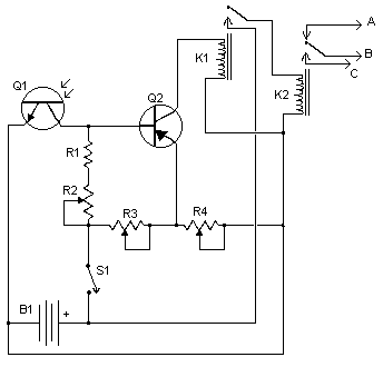
Circuit diagram
Parts:
- R1 5K 1/4W Resistor
- R2, R3, R4 5K Pot
- Q1 NPN Phototransistor
- Q2 2N3906 PNP Transistor
- K1 Low Current 12V SPST Relay
- K2 High Current 12V SPDT Relay
- S1 SPST Switch
- B1 Car Battery
- MISC Case, wire, board, knobs for pots
Notes:
- Q1 should be mounted in such a way so it points toward the front of the car with a clear line of site. Suitable places are on the dashboard, in the front grill, etc.
- Adjust all the pots for proper response by testing on a deserted road.
- S1 enables and disables the circuit.
- B1 is, obviously, in the car already.
- Before you try to connect this circuit, get a wiring diagram for your car. Some auto manufacturers do weird things with wiring.
- Connection A goes to the high beam circuit, B goes to the headlight switch common and C connects to the low beam circuit.
