- Car Headlights Timer Circuit: Build Your 1min 30sec Delay
- Build Your Motor Bike Headlight Controller Circuit
- Build Your Own 30V LED Bike Light Circuit
- Build Your 12V Headlight Reminder Circuit with a Buzzer
- Fog Light Circuit: Trailer Connection & Relay Control
- Build a 13-Way Optocoupler Fog Lamp Sensor Circuit
- Car Bulb Flasher Circuit Diagram: 12V 21W Flashing Lights
- Automobile Fader Circuit Diagram: 700Hz & 5s Fade
- DIY Headlight Timer Circuit: 1 Minute Delay Build
- Automatic Headlight Brightness Switch – Build Your Smart Circuit
Car Bulb Flasher Circuit Diagram: 12V 21W Flashing Lights
Description
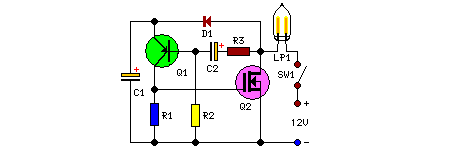
This remarkably straightforward circuit enables the operation of one or two robust 12V 21W automobile lamps in a flashing configuration, utilizing a power MOSFET. Such devices are especially appropriate for roadway, traffic, and outdoor area warnings, and are applicable in every situation where alternating current power is unavailable, yet a bright flashing light remains required.
Circuit Diagram:
Parts:
- R1 = 6.8K
- R2 = 220K
- R3 = 22K
- C1 = 100uF-25V
- C2 = 10u-25V
- D1 = 1N4002
- Q1 = BC557
- Q2 = IRF530
- LP1 = 12V-21W Car Filament Bulb (See Notes)
- SW1 = SPST Switch (3 Amp minimum)
More about components
The BC557 is a general-purpose NPN bipolar junction transistor. This component is frequently used in switching applications due to its moderate current gain and relatively low saturation voltage. The 1N4002 is a silicon diode, a two-terminal electronic component that conducts current in one direction only. It protects the circuit from reverse voltage damage. These integrated circuits are selected for their reliability and performance within the intended circuit operation.
Notes:
- Flashing frequency can be adjusted within a restricted range by modifying the value of C1.
- Considering the involvement of substantial direct currents, please utilize appropriately sized cables for connections to the battery and the bulb(s).
Security Warning
Working with electrical circuits involving batteries and high currents carries inherent risks. Incorrect wiring or component selection could result in electrical shock, fire, or damage to equipment. Always exercise caution and consult a qualified electrician if you are unsure about any aspect of this project. The author and source of this circuit diagram take no responsibility for any damages or injuries that may occur as a result of using this information.
