Build Your Own 1458 Radar Detector Circuit Diagram
Circuit Diagram
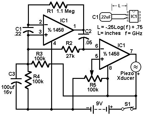
A radar detector circuit is illustrated here, employing a 1458 dual operational amplifier. C1 functions as the radar signal detector. The initial op-amp is configured as a current-to-voltage converter, while the subsequent op-amp provides buffering to drive the piezo transducer. The resistor R5 is utilized to define the switching threshold within the second op-amp; it's generally calibrated so that the circuit only activates in response to background noise, and then slightly adjusted. The circuit's behavior can be fine-tuned by modifying the length of the leads attached to C1. For conventional road-radar applications, the input capacitor’s leads should ideally measure approximately 0.5 to 0.6 inches in length.
Dual Operational Amplifiers
The core of this circuit relies on a 1458 dual operational amplifier. These integrated circuits are complex semiconductor devices that amplify and process electrical signals. They are commonly used in numerous applications, including audio amplification, signal processing, and instrumentation. The 1458 dual op-amp consists of two independent amplifier stages housed within a single integrated circuit package. Each stage can operate independently or in a cascaded configuration to achieve specific amplification or filtering characteristics. The device operates on bipolar technology and can be powered by a single supply voltage, simplifying circuit design. The 1458 op-amp family offers a wide range of performance specifications, including high gain, low noise, and fast slew rates, making them suitable for demanding applications. Their versatility and readily available packaging have made them a staple component in electronic circuits for decades. The device typically operates at a supply voltage of +/- 15V and can handle input signals ranging from -1V to +10V. Careful consideration must be given to thermal management when designing circuits utilizing this IC due to its power dissipation characteristics.
circuit from http://www.electronics-lab.com/
