Audible Flasher Delay Circuit: Build Your Warning System
Description
If you are a motorcycle or scooter operator, you will understand the difficulty of forgetting to deactivate flashing lights after a turn, without a distinct auditory alert. Continuously observing indicator lamps is impractical; attention must remain focused on the road ahead! The presented circuit provides a helpful, audible notification. The ingenious aspect is its design, preventing irritation by generating a beep only after a specified timeframe, essentially signaling when the indicators remain active for an extended duration. Power to the circuit is supplied via the flasher relay.
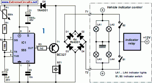
When the indicators are activated, a squarewave voltage reaches the bridge rectifier D1-D4 through terminals T1 or T2, while the remaining terminal is grounded through the inactive indicator lamp. The pulsed direct current (DC) voltage is stored and leveled by capacitor C1, with D5 preventing the electrolytic capacitor from discharging when the flasher voltage is absent. This also furnishes a sufficiently pure voltage supply for the 555 timer IC during indicator operation. Timer IC1 functions as an oscillator and controls a piezoelectric sounder using transistor T1.
555 Timer IC
The 555 timer IC is a versatile integrated circuit frequently employed as an oscillator or timer in various electronic circuits. This particular IC is known for its ability to generate a stable time delay or pulse width. It operates by utilizing a positive feedback loop to create a self-oscillating circuit. The 555 timer is available in several package types, including single, dual, and triple versions, offering different configurations for specific applications. The IC’s performance is dependent on the values of the external resistors and capacitor, which are carefully selected to achieve the desired timing characteristics. Furthermore, the 555 timer is capable of operating in different modes, such as astable (oscillating), monostable (one-shot), and bistable (flip-flop), providing flexibility in circuit design. The IC's reliability and readily available support contribute to its widespread use in hobbyist and professional applications alike.
Circuit diagram:
The output of the 555 timer is active Low, meaning that initially, the transistor is non-conducting and the sounder remains silent. The timer continuously charges and discharges capacitor C2 to a level between one-third and two-thirds of the operating voltage, generating a time interval of 0.7 x C2 x (R2 + R1 + P1) [s]. The adjustable potentiometer enables you to configure this delay up to approximately one second. The initial delay, before the sounder first operates, is considerably longer, however, because the electrolytic capacitor has no initial charge. Only after this delay is the output activated, for a duration equivalent to 0.7 x C2 x R2 (approximately 0.15 seconds), allowing the sounder to function.
This applies solely when +12 V is present at the collector of transistor T1, which corresponds to the situation when the flasher relay is simply switched on, and the indicator bulbs illuminate. The circuit is housed within a weather-resistant enclosure, installed on your machine in a protected location. The audible sounder can be positioned anywhere outside the enclosure if it’s a waterproof type. The audible control unit requires only two cable connections, which can be made at any convenient access point.
circuit from http://www.extremecircuits.net/2010/05/audible-flasher-warning.html
