- Build Your "Who's First" Game Indicator Circuit!
- Build Your Own Electronic Dice: A 9V Circuit Design
- Build Your Digital Roulette Circuit Diagram
- Build Your Own 4017B Electronic Dice Circuit Diagram
- Build a Brilliant 30-Socket Circuit Game Schematic
- Build Your Magnetic Gun: A 18V Circuit Design
- Build Your 4 Input Quiz Circuit Diagram
- Build a Magnetic Circuit: The 1-2-3 Wand Trick
Build Your Magnetic Gun: A 18V Circuit Design
Circuit Diagram
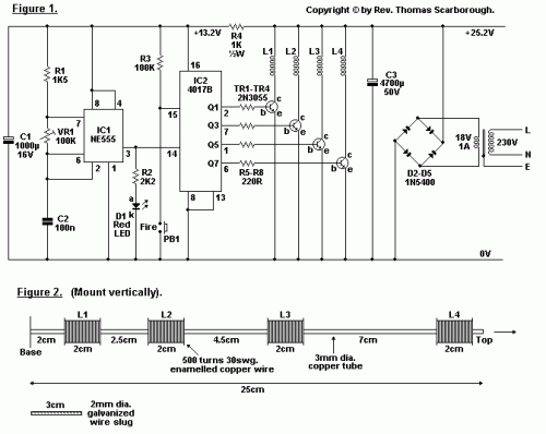
A miniature magnetic weapon is illustrated in Figure 1. When properly configured, it will launch a small projectile approximately 1.5 meters vertically, or 2.5 meters horizontally.
Integrated circuits play a vital role in this system. IC1 is a 555 timer operating in astable mode, generating approximately 10 millisecond pulses which are then sent to decade counter IC2. IC2 is continuously reset via resistor R3 until pin 15 receives a low signal from the "Fire" button. Consequently, IC2 sequences through outputs Q1 to Q7, subsequently powering transistors TR1 to TR4 to activate the electromagnets L1 to L4 in a rapid succession.
Transformer T1’s secondary winding provides 18 volts at 1 amp of alternating current. After rectification and smoothing, this delivers 25.2 volts direct current, sufficient for the operation of electromagnets L1 to L4. Resistor R4 reduces the voltage to a level suitable for IC1 and IC2.
The electromagnets are wound upon a 25 centimeter long, 3 millimeter diameter copper tube, readily available at hobby shops. Two stops can be fashioned from tin for each electromagnet, and approximately 500 turns of 30 swg enamelled copper wire are wound around them. The electromagnets should be wound onto a base secured with reversed sellotape, allowing for sliding movement along the copper tube. The projectile, or “bullet”, is a 3 centimeter long piece of 2 millimeter diameter galvanized wire, designed to slide freely within the copper tube.
Crucially, the setting of VR1 and the positioning of electromagnets L1 to L4 on the copper tube (the values and measurements shown are merely a guideline) are fundamental to the system’s performance. Initially, with L2 to L4 disconnected, VR1 should be tuned and L1 positioned for optimum effectiveness (place a wire inside the tube to assess how far the slug jumps with L1). Then, L2 (now connected) should be positioned for optimal performance (the slug will now exit the tube). Repeat this process with L3 and L4.
It was found that electromagnets L2 to L4 significantly enhanced the range of the weapon. Further details on achieving this will be presented in a future edition of EPE, where the author details how readers can successfully land a small projectile on Mars.
circuit from http://www.electronics-lab.com/
