- Build Your "Who's First" Game Indicator Circuit!
- Build Your Own Electronic Dice: A 9V Circuit Design
- Build Your Digital Roulette Circuit Diagram
- Build Your Own 4017B Electronic Dice Circuit Diagram
- Build a Brilliant 30-Socket Circuit Game Schematic
- Build Your Magnetic Gun: A 18V Circuit Design
- Build Your 4 Input Quiz Circuit Diagram
- Build a Magnetic Circuit: The 1-2-3 Wand Trick
Build Your Own 4017B Electronic Dice Circuit Diagram
Description
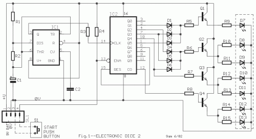
The NE555 or LM555 timer IC is utilized in this circuit for astable operation. Clock pulses are supplied to the 4017B IC2 via a 10K resistor. The 4017B IC2 functions as a 10-stage counter, with output 6 (pin 5) connected to the RESET (pin 15) terminal, resulting in a 6-stage counter producing outputs ranging from 0 to 5. Six LEDs are arranged in three pairs, necessitating four distinct signals originating from the four transistors. These transistors are powered from multiple outputs of the IC2, and diodes are employed to prevent short circuits between the outputs. A 100K resistor connects pin 13 of the IC2 (INHIBIT) to the positive voltage supply, halting the counter's progression. Pressing the S1 [START] push switch connects pin 13 to ground, enabling the counter to advance, thereby initiating the dice rolling function. The circuit can be powered by a 9V battery or an external power supply providing voltage from 9 until 12V.
4017B
The 4017B is a widely used CMOS decade counter IC. It is a programmable counter that can count from 0 to 9. It is a versatile component frequently found in digital logic circuits and displays. It operates from a supply voltage of 5V.
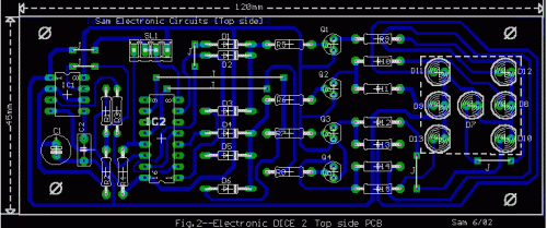
Circuit diagrams
Part list
- R1-2=2.2Kohms
- R3=10Kohms
- R4=100Kohms
- R5.....8=8.2Kohms
- R9.....5=1Kohms
- C1=22uF 25V
- C2=10nF 100V MKT
- D1.......6=1N4148
- D7.......13=Red Led 5mm
- IC1=NE555 or LM555
- IC2=4017B
- Q1....4=BC550
- S1=Normal Open Push switch
- SL1=4pin connector 2.54mm step
- BATT=9V battery or 12V ext.
circuit from http://users.otenet.gr/~athsam/electronic_dice_2.htm

