- Build Your "Who's First" Game Indicator Circuit!
- Build Your Own Electronic Dice: A 9V Circuit Design
- Build Your Digital Roulette Circuit Diagram
- Build Your Own 4017B Electronic Dice Circuit Diagram
- Build a Brilliant 30-Socket Circuit Game Schematic
- Build Your Magnetic Gun: A 18V Circuit Design
- Build Your 4 Input Quiz Circuit Diagram
- Build a Magnetic Circuit: The 1-2-3 Wand Trick
Build Your Own Electronic Dice: A 9V Circuit Design
Description
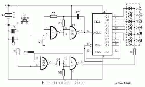
This particular circuit functions as an accidental number generator, producing figures ranging from 1 to 6. This behavior is observed through a line connected to an LED, where each one corresponds to a number from 1 to 6, triggered by pushing and releasing switch S1. This movement mimics the action of rolling a dice. The LED that illuminates will remain lit for approximately five to ten seconds before extinguishing, awaiting the next activation. The electronic dice, designed to emulate a real dice, requires an “it stops” function utilizing one of the six LEDs activated sequentially, each representing one of the six sides of a standard die. A single LED turns on in a defined sequence and remains lit until the switch S1 is released. The circuit can be divided into two distinct sections; one focused on providing the clues, and the other managing the timing and control signals. The final component of the circuit is suggested through the implementation of two classic circuits, namely the ‘astable’ circuit, utilizing IC1a-c, and the ‘monostable’ circuit, employing ICβ-D. The pulse signal generated by the ‘astable’ circuit is directed to IC2. This IC possesses ten output terminals. Each output terminal is activated sequentially by the incoming pulse signal. Within this circuit, the goal is to achieve a count up to six. To accomplish this, the seventh output of IC2 is connected to the reset input (15) of the same IC. When output 5 transitions to a high state, the counter is reset to its initial value. The LEDs are activated by the outputs of IC2 that are at a high voltage level. They illuminate when the common point, formed by the cathode of the LED and R6, experiences a low voltage. R6 is connected to the output of ICβ-D. This point consistently maintains a high voltage level, ensuring that all LEDs remain off (extinguished). Upon releasing switch S1, the input of IC1B, via C3 and R1, experiences a temporary low voltage, activating the output of this gate. C4 transmits this change to the input of ICβ-D, forcing the output of this gate to transition to a low voltage, thus reactivating the clue. R5 discharges C4, restoring the circuit to its original condition after a predetermined duration. The R6 limits the current flowing through the LEDs, protecting them from excessive current. The power supply for the circuit originates from a 9V battery, providing ample power without requiring frequent replacements, and the circuit consumes minimal energy even during short periods of operation, rendering the switch an unnecessary component.
Circuit diagram
Part List
- R1-3-5= 100Kohms
- R2= 10Kohms
- R4= 56Kohms
- R6= 470 ohms
- C1-4= 100uF 16V
- C2= 100 nF 63V MKT
- C3-5= 10nF 63V MKT
- IC1= 4011
- IC2= 4017
- D1-6= LED Red 5mm.
- S1= Push button switch
- BATT= 9V battery
